Seats/rear swingarm/rear hub/sprocket etc
Categories: Construction Progress
Written By: roo
Should the caption go at the top…well that’s how it’s to be…Here are the seat bottom frames, they are 1″-.065 6061 and they come out, so if I decide they are not the most comfy, I can change them!
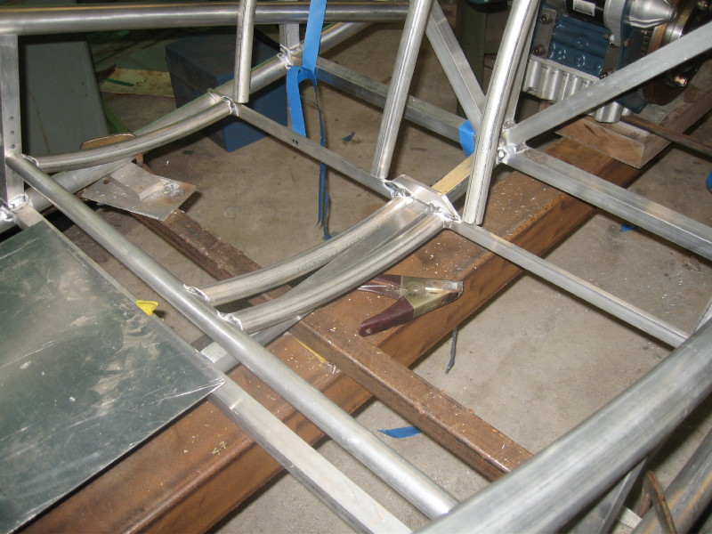
The backs will look something like this, they will stop just above that horizontal tube…they will get a little bend just at “lumbar” height for good back support…I hope…also they will pivot forward (there is a little space back there for stuff)
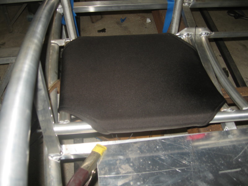
Here is a seat bottom in place it is 1000 deneir “ballistic” nylon with two layers of neoprene wetsuit material under it to pad the tubes…it is laced tightly across the back (sorry I forgot to take that pic) and from what I can tell so far pretty comfy…the seat backs will be made the same way, but they hopefully will be a heavy mesh to keep the back cool…
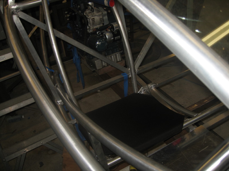
I like the corner detail…plus it was the easiest way to have the fabric fit the frame…
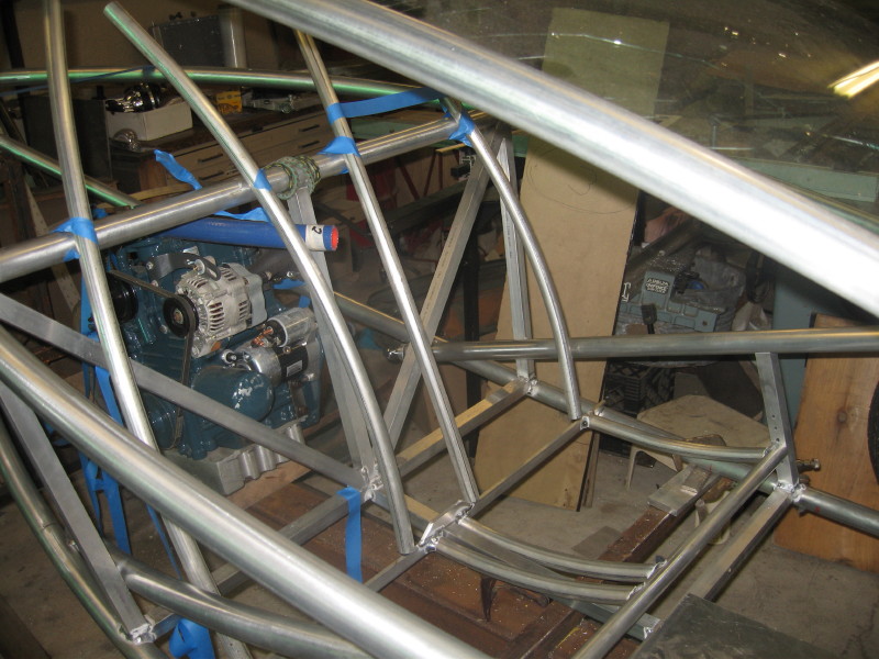
OK…here is the rear swingarm, sorry the pics are a bit jumbled…but this is a overall view…please note that this is not the complete structure, there is a sort of “kinpost” triangulation going to happen around the engine and wheel…wait and see…
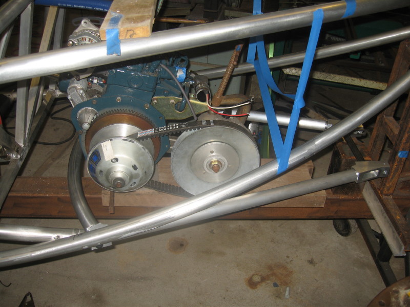
This curved tube ties the front of the swingarm together, and prrovides for the forward anti vibration mounts for the engine…(yes the engine mounts to the swingarm…but it is centered over the pivot so there should be minimal engine unsprung weight issues…
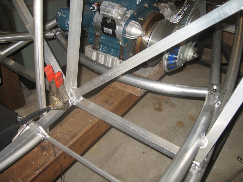
rear view of the same…I have to add to my jig to provide a accurate location for the rear axle…
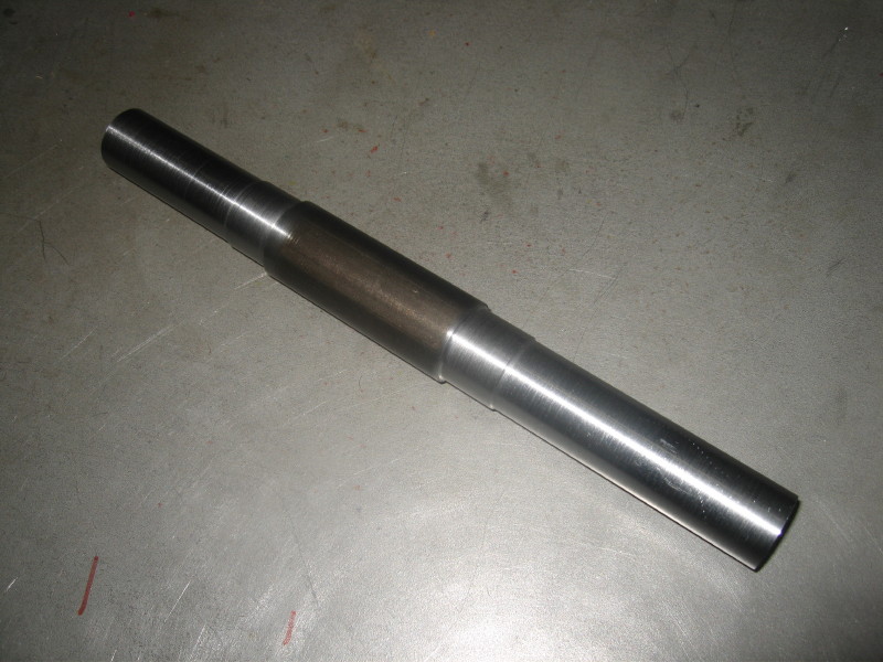
here is the actual rear axle…it is machined out of a piece of high strength “stressproof” steel the big part goes between the bearings and locates the axle…
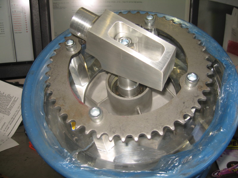
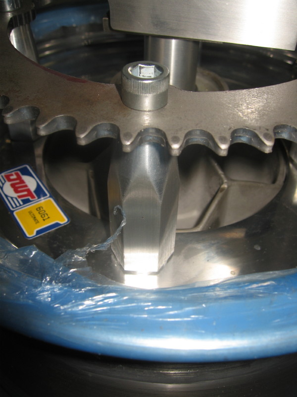
Here is the rear wheel with hub, axle mount, and sprocket all mounted…note the hex “standoffs” that hold the sprocket, they screw onto the lugs from the hub in place of lug nuts…the sprocket is a standard 48 tooth sprocket with the new bolt circle drilled and the middle machined out…see sometimes I do machine steel…
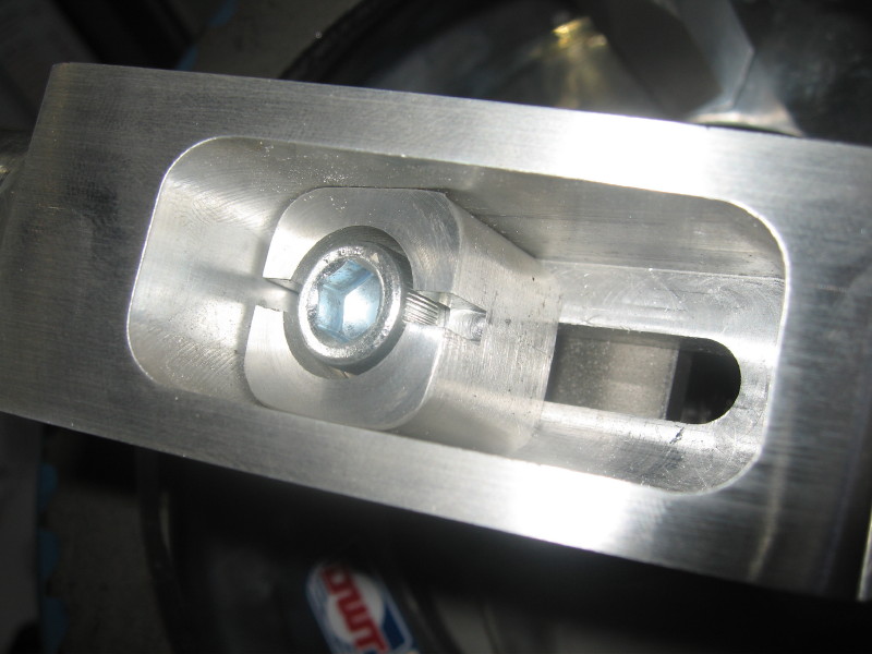
a close-up of the sprocket….I probably could have used 5/16-24 sockethead cap screws here instead of the 3/8-24 one that i did…
here is the rear axle adjuster showing the screw head that will be drilled in three places for a cotter pin…
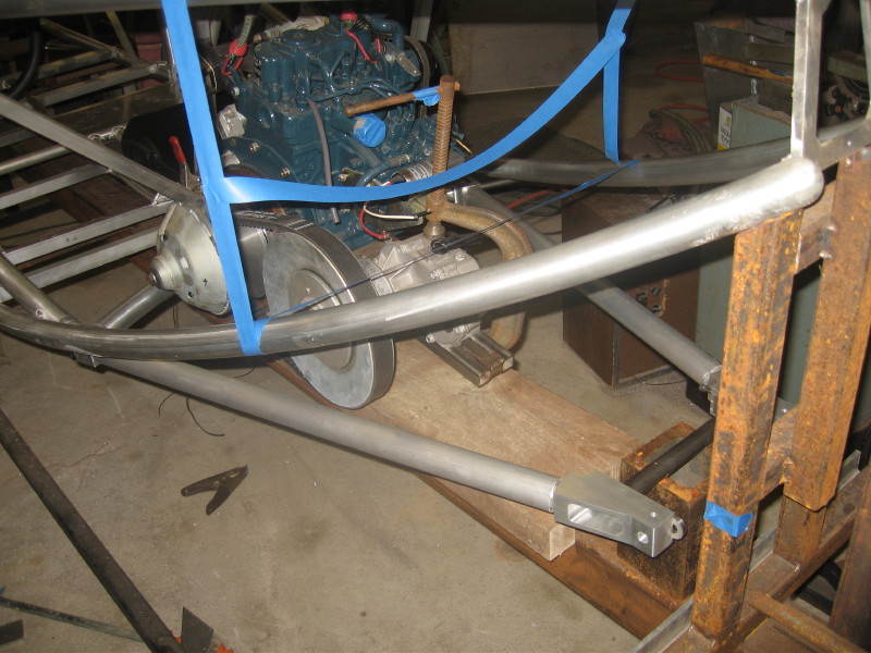
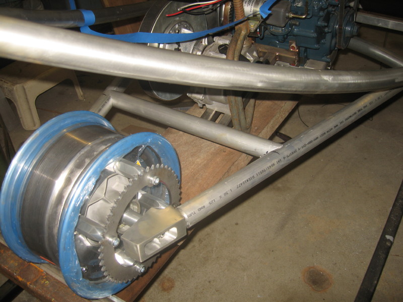
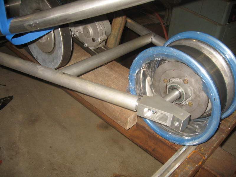
here is the swingarm with the rear wheel mounted…the cross-tube is in place that holds the rear shock bottom and the motor rear anti-vibration mount…
the other side…the brake disk is visable…the caliper will be mounted on a bracket that rides on the rear axle and is anchored in that hole in the back of the axle adjuster…I found a nice caliper that has a combo hydro-and mechanical action, so I can use it for the regular brakes, and the emergency/parking brake….
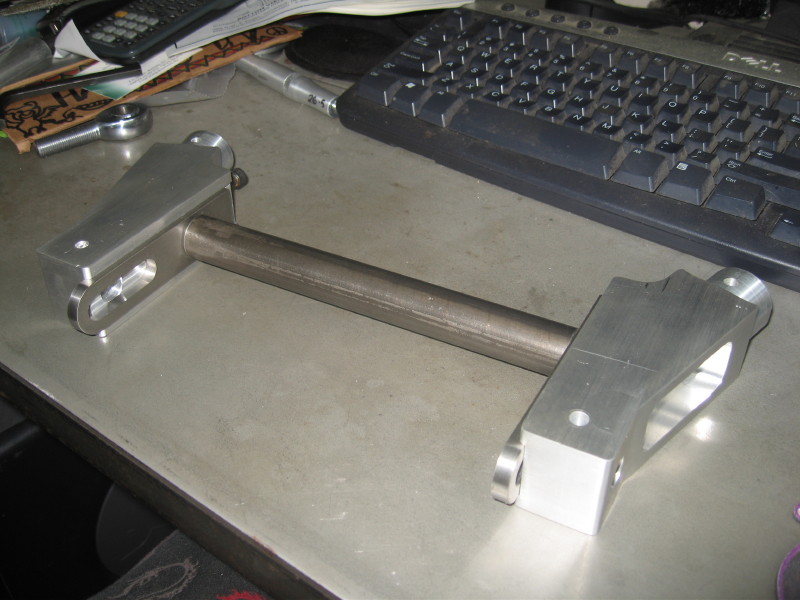
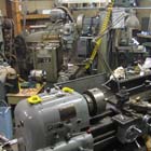
some machining pics…these are the axle adjusters, and the swingarm pivots they took 12″ off my 4-1/2″ x 1-1/2″ 6061 bar!
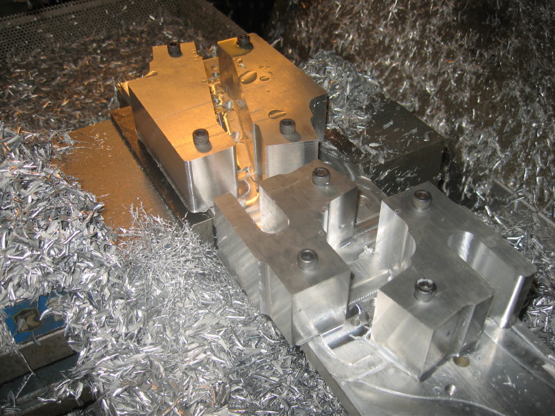
each piece got a rounded end to go inside of the 1-1/2″ tube…I did this in the cnc with a ball end mill…so that there was a good bevel for the weld bead…
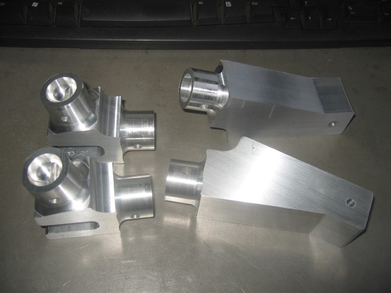
the pivots showing the 1/2″ heim that is the pivot…
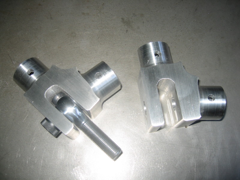
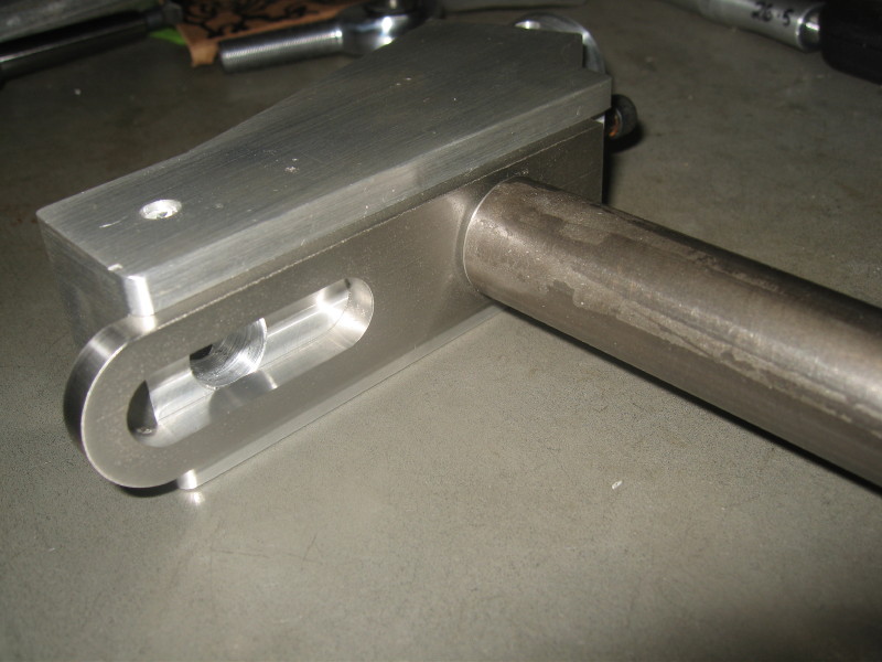
the picture below shows the axle adjusters with the stainless plate that has a counterbore for the axle…I wanted to make sure that I had a good hard seat for the axle…thought the aluminum might be too soft there…the slot is so I can adjust the axle, and still mount the brake caliper in the right place…
closeup…


February 5th, 2012 at 4:39 pm
Am i correct in assuming you need no clutch in this kubota, variable pulley drive setup? that at idle the “drive” pulley is gapped enough to not engage the belt and “driven” pulley?
Im interested in doing a similiar setup with a kubota 3 cyl diesel for a 1/8 scale 7.5 gauge train…but i need reverse too… still researching…