
Here are some more pictures of the ‘pod in it’s current state taken by my friend Ford Bailey it’s amazing what a real photographer with a real camera can do! enjoy…
[nggallery id=6]
Here are some more pictures of the ‘pod in it’s current state taken by my friend Ford Bailey it’s amazing what a real photographer with a real camera can do! enjoy…
[nggallery id=6]
I showed roopod at altwheels fleet day Monday and was a bit lazy with my camera (read no pictures) but I found this one on cnet…this is in front of Staples World Headquarters it was a fun event and I got to talk a lot of tech talk with all the big truck bigwigs! almost everyone was in a suit! Bill Buchholz was there with Dirago (background in the picture) and it was fun hanging out with him, probably the most interesting bit was a talk with the guy from Valence batteries (www.valence.com) about what it would take if I wanted to make roopod have an electric poweplant option I was surprised that he predicted that I would need only 71 kg (156lb) of batteries to have a 100 mile range I would get rid of 150 lb of diesel engine, get that back with the batteries, and then maybe another 100lb for the elec motor etc…not near as bad as I thought…they would have to give me those batteries, though….probably about $20,000.00 worth!!!…guess that’s about it for altwheels! thanks for looking…plus here is some press they got…not much to do with roopod…but interesting none the less…
http://www.necn.com/Boston/SciTech/2009/10/05/Cherry-pickers-go-from-seeing/1254775077.html
http://news.cnet.com/8301-11128_3-10367683-54.html
http://www.boston.com/news/science/articles/2009/10/06/alternative_energy_vehicles_on_exhibit/
http://www.metrowestdailynews.com/news/x2060103328/Alternative-fuel-fleets-showcased-at-Staples


Attend altwheels festival! roopod will be there…

Come Join Us at Staples World Headquarters
![]() Fifth Annual AltWheels Fleet Day
Fifth Annual AltWheels Fleet Day
![]() — Monday, October 5th, 2009 – 8:30a to 3:30p —
— Monday, October 5th, 2009 – 8:30a to 3:30p —
not much to say here, I got to show the ‘pod at the hometown festival…there was an impressive amount of car tech knowledge there!
[nggallery id=5]
My apologies, I was so crazed trying to get ready for the OGC that I neglected regular posts for a couple weeks there, and now this post is going to be big….again sorry…
First, the pictures:
[nggallery id=4]
these pictures include pictures of construction progress leading up to the OGC and pictures at the start of the OGC in Greefield, MA, and Pictures at the finish in Boston, MA, and some pictures out in the yard yesterday. here are some links to press coverage as well
http://www.necn.com/Boston/SciTech/2009/08/20/Drivers-take-on-One-Gallon/1250806914.html
http://green.autoblog.com/2009/08/24/one-gallon-challenge-alt-fuel-race-cars-get-up-to-164-mpge/
this is the report by Jory Squib that is on the autoblog green sight:
This weekend’s One Gallon Challenge in Massachusetts resulted in some pretty amazing fuel economy results. The five vehicles that took part in the race challenge (any line of of cars that starts “in stately, fuel-conserving style” can’t really be called a race, can it?) made the 100-mile drive into Boston and posted fuel efficiency results as follows:
OGC organizer Jory Squibb said the vehicles helped show solutions for “our complex evolution to ultra-economy” and promised to hold the event again next year. Fun fact of the trip: the MIT Porsche recharged at a 220V outlet at a local Ford dealer.
Ten!…Nine!….Eight!….the spectators shouted the count-down until Nancy Hazard dropped the checkered flag in front of six unusual cars. Without the screech of tires, the One Gallon Challenge began in stately, fuel-conserving style, as each car set out to drive the 100 mile trip from Greenfield to Boston on one gallon of fuel.
As the cars pulled into the Greenfest festival in downtown Boston later that afternoon, after blisteringly hot weather and many adventures, each had proven some aspect of our complex evolution to ultra-economy.
Dirigo–a sleek diesel 3 wheeler clocked in at 88MPGe with a running cost of 2.9 cents per mile–showed the importance of good aerodynamics. This car had not only driven the 100 mile segment without back-up, but also driven the 450 mile round-trip from Maine. With a sigh, Bill Buchholz finally pointed the hood North.
Ricker Truck, also 900cc diesel-powered, clocked in at 70 MPGe and showed the advantages of using laminated foam construction for safety and light weight. This car was finished only hours before the race.
The wood-gas powered truck from 21st Century Motor Works breezed in at 27.7 MPG, showing the viability of using a local, carbon-sequestering fuel source: ordinary cord wood.
MIT’s electric vehicle team drove their lithium Porche in at an amazing 164 MPGe (plug-to-wheels) and 75MPGe (wells-to-wheels) Once our electricity grid becomes more earth-friendly, this technology may lead all others. Many spectators, used to lead-acid technology, were awed as these students drove their Porche, with 15 automotive-sized batteries, from Cambridge to Greenfield on a single charge, then charged up with 220v at the Ford dealership, and merrily drove back home. Without a doubt, the miracle battery we all dreamed of decades ago has arrived.
The Roopod, poster-child of the event, was not quite drivable at race time, but was on display both in Greenfield and in Boston. This ultra sleek and light, 14 HP diesel-powered wonder will be a car to be reckoned with next year.
Dripping with sweat, Jory Squibb drove his gas-powered three-wheel Moonbeam across the line at 93 MPGe and 2.7 cents per mile cost. Built as a grocery-getter, it had never been driven far from Camden, Maine; but finished the race without incident, blasting its heater to keep the engine cool in the 90 degree heat.
Though they were weary after interacting with the thousands of attendees of the two-day Greenfest, all participants agreed to return next year with new developments and face an even larger field of next-generation transportation.
Here are some articles just come out…hope the links work…sorry if you can’t get to them without paying…you still have to buy your paper…lol…Roo
(this is a front page picture)
http://www.boston.com/news/globe/larger_view/?g_date=2009_08_17
(this is the actual article)
http://www.boston.com/lifestyle/green/articles/2009/08/17/the_race_is_on_100_miles_on_just_1_gallon/
this is the Greenfield Recorder article
http://www.recorder.com/story.cfm?id_no=6474048
This is basically the same as the Recoder, but in the next town over paper…The Daily Hamshire Gazette
Hi there, Everybody! It Rolls! yeah! ok-ok enough…
I am very tired, I stayed up till three last night working on steering arms etc, and I don’t have the energy to caption all the pictures: So here is a brief overview caption…
there are pictures of parts provided by Greasecar to convert the ‘POD to be able to run on veggy oil, or 100% biodiesel all winter (thanks Greasecar!) and a picture of the wire harness provided by Rebel Wire (Thanks Rebel Wire)…look on the links page for their links…and there are some pictures of the steering wheel “frame” getting machined…will have a wood core around the rim…and wrapped with leather…it’s 10-1/2″ in Dia, and then the pictures I have been waiting for for more than a year…It rolls…That’s Leilani, my daughter in the yellow hoody and that’s our “big” car the VW New Beetle! Then there are some pictures of the ‘Pod next to my friend Bob’s Miata…the Miata is pretty big too! Then that’s My partner Susan, and My freind Bob taking a ride in the ‘Pod…I am very happy So far, most everything is working like I thought it would! Hopefully I will come back and fix this post a bit when I am not quite so tired!
I also just added this Youtube video of the ‘POD in action!
Thanks for looking...Roo
[nggallery id=3]
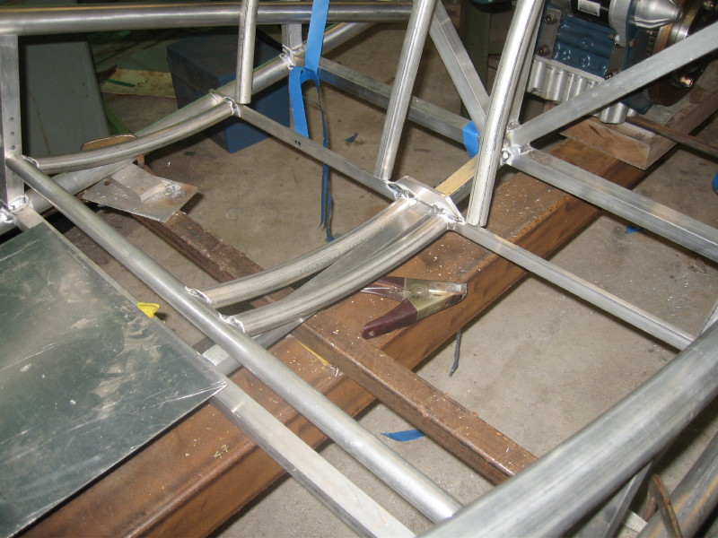
Should the caption go at the top…well that’s how it’s to be…Here are the seat bottom frames, they are 1″-.065 6061 and they come out, so if I decide they are not the most comfy, I can change them!
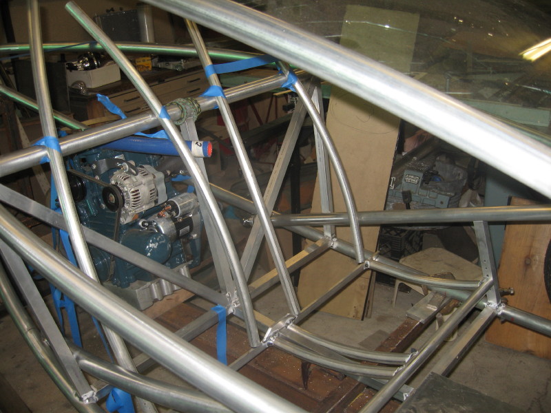
The backs will look something like this, they will stop just above that horizontal tube…they will get a little bend just at “lumbar” height for good back support…I hope…also they will pivot forward (there is a little space back there for stuff)
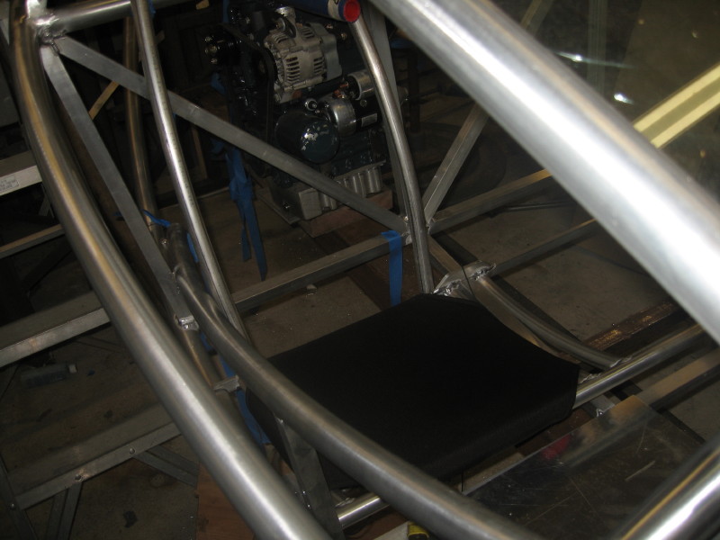
Here is a seat bottom in place it is 1000 deneir “ballistic” nylon with two layers of neoprene wetsuit material under it to pad the tubes…it is laced tightly across the back (sorry I forgot to take that pic) and from what I can tell so far pretty comfy…the seat backs will be made the same way, but they hopefully will be a heavy mesh to keep the back cool…
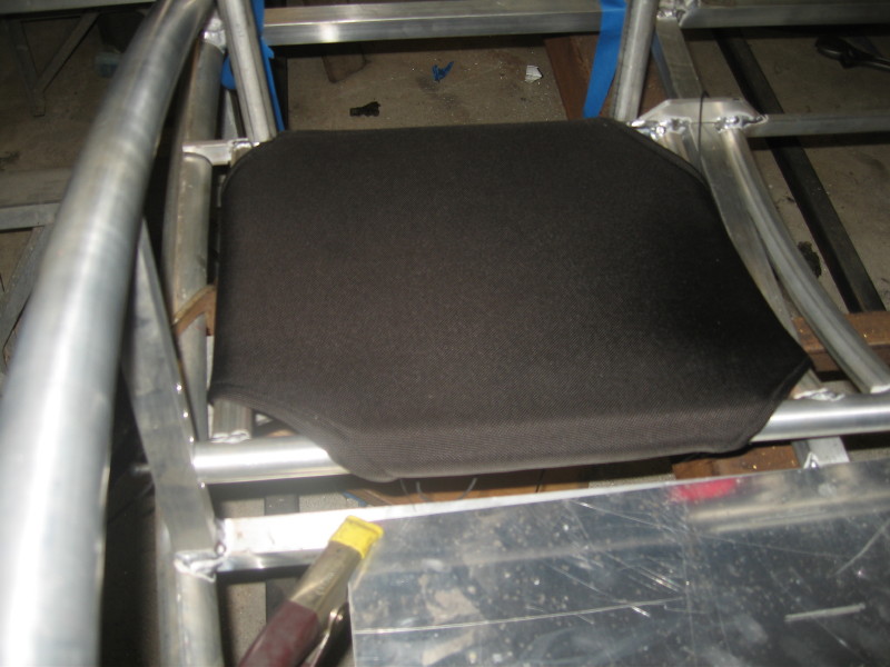
I like the corner detail…plus it was the easiest way to have the fabric fit the frame…
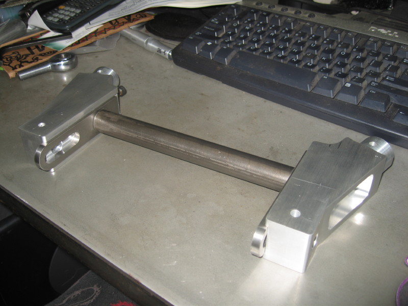
OK…here is the rear swingarm, sorry the pics are a bit jumbled…but this is a overall view…please note that this is not the complete structure, there is a sort of “kinpost” triangulation going to happen around the engine and wheel…wait and see…
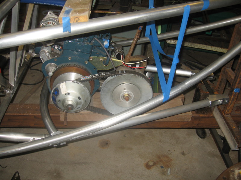
This curved tube ties the front of the swingarm together, and prrovides for the forward anti vibration mounts for the engine…(yes the engine mounts to the swingarm…but it is centered over the pivot so there should be minimal engine unsprung weight issues…
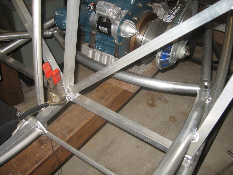
rear view of the same…I have to add to my jig to provide a accurate location for the rear axle…
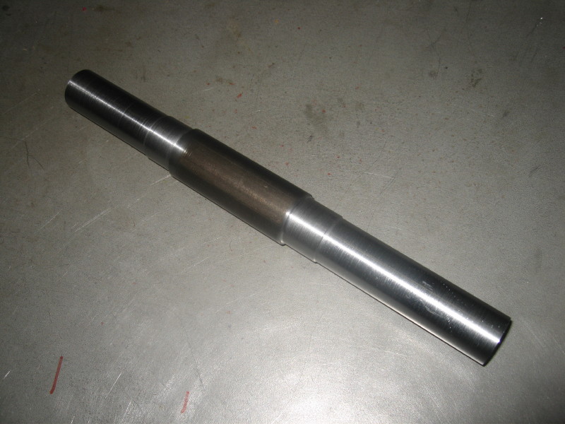
here is the actual rear axle…it is machined out of a piece of high strength “stressproof” steel the big part goes between the bearings and locates the axle…
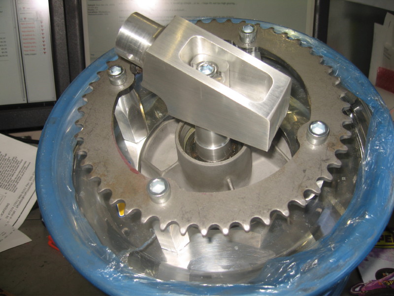
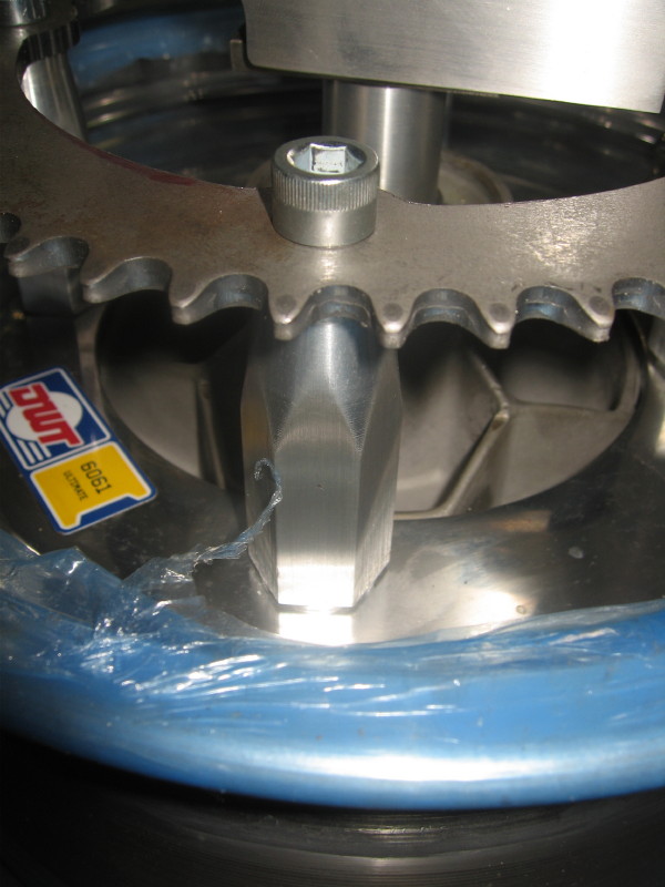
Here is the rear wheel with hub, axle mount, and sprocket all mounted…note the hex “standoffs” that hold the sprocket, they screw onto the lugs from the hub in place of lug nuts…the sprocket is a standard 48 tooth sprocket with the new bolt circle drilled and the middle machined out…see sometimes I do machine steel…
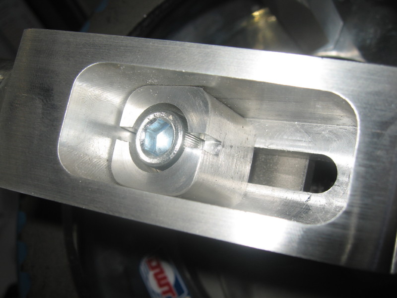
a close-up of the sprocket….I probably could have used 5/16-24 sockethead cap screws here instead of the 3/8-24 one that i did…
here is the rear axle adjuster showing the screw head that will be drilled in three places for a cotter pin…
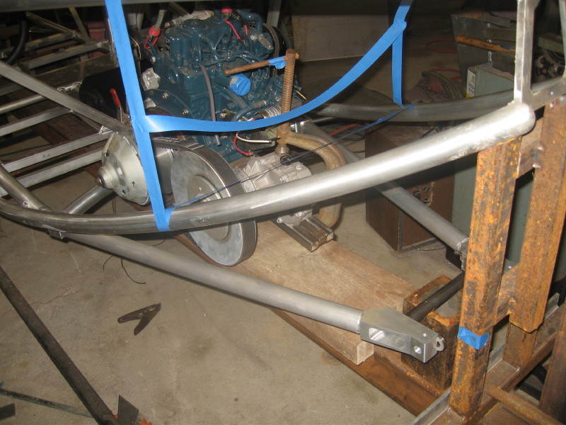
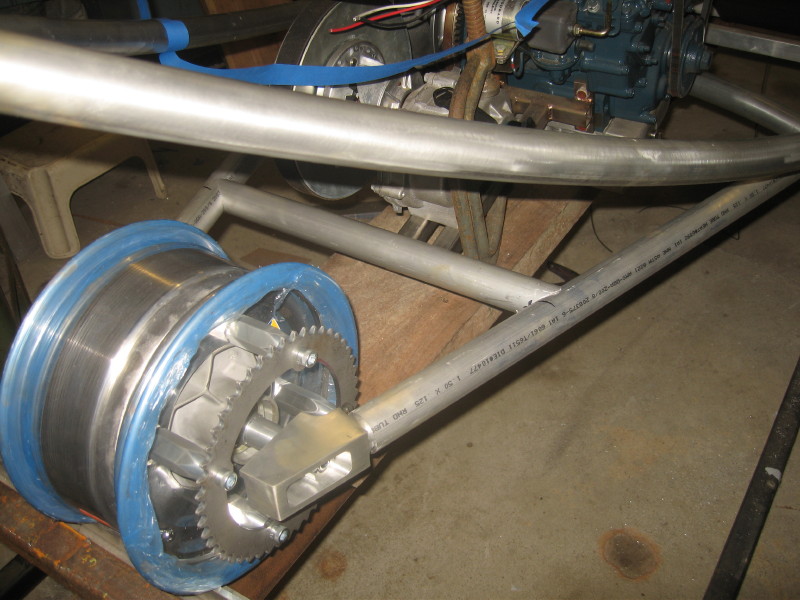
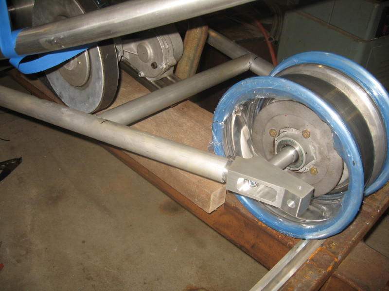
here is the swingarm with the rear wheel mounted…the cross-tube is in place that holds the rear shock bottom and the motor rear anti-vibration mount…
the other side…the brake disk is visable…the caliper will be mounted on a bracket that rides on the rear axle and is anchored in that hole in the back of the axle adjuster…I found a nice caliper that has a combo hydro-and mechanical action, so I can use it for the regular brakes, and the emergency/parking brake….
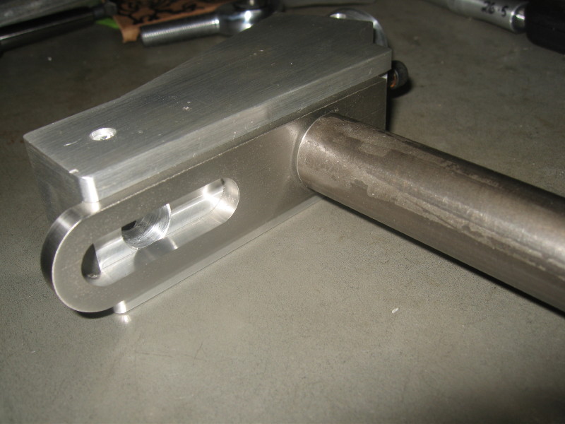
some machining pics…these are the axle adjusters, and the swingarm pivots they took 12″ off my 4-1/2″ x 1-1/2″ 6061 bar!
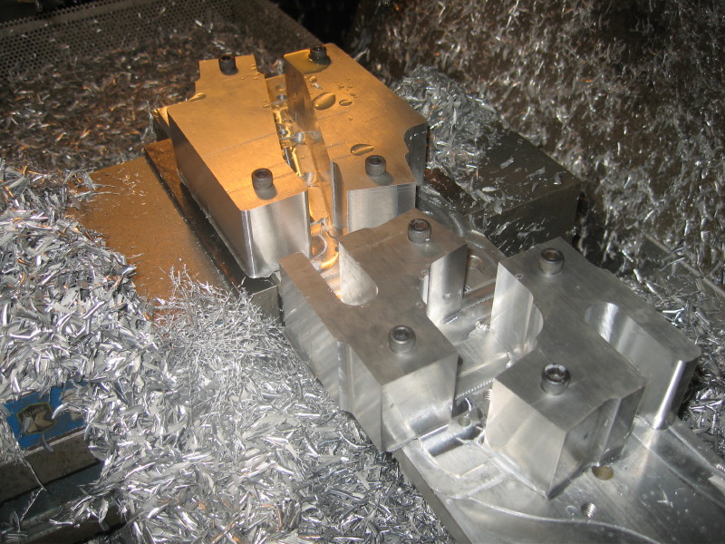
each piece got a rounded end to go inside of the 1-1/2″ tube…I did this in the cnc with a ball end mill…so that there was a good bevel for the weld bead…
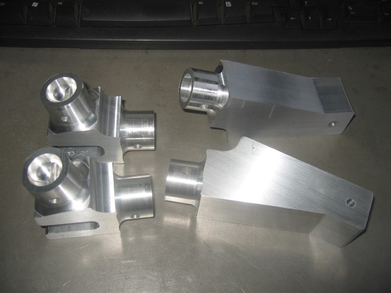
the pivots showing the 1/2″ heim that is the pivot…
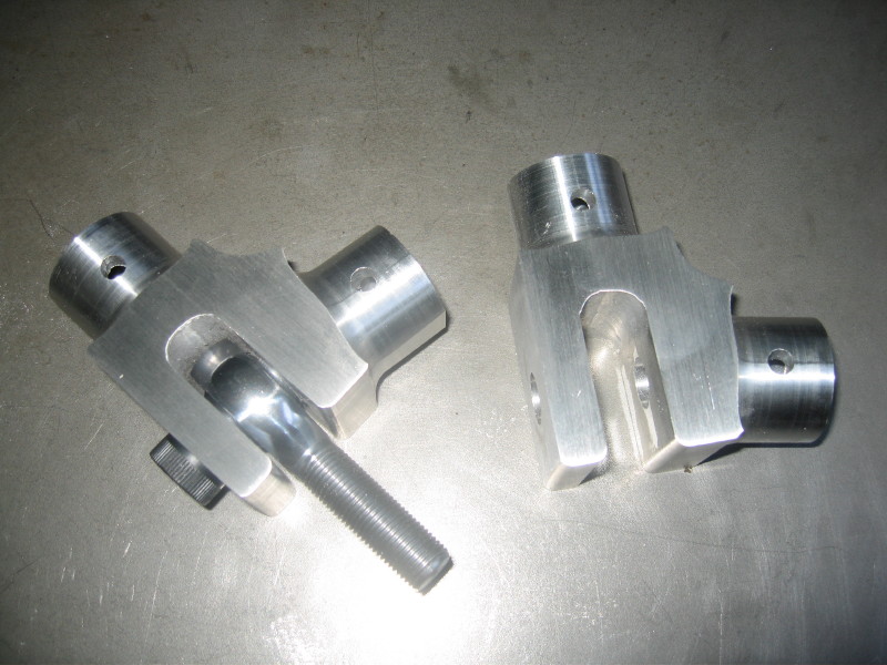
the picture below shows the axle adjusters with the stainless plate that has a counterbore for the axle…I wanted to make sure that I had a good hard seat for the axle…thought the aluminum might be too soft there…the slot is so I can adjust the axle, and still mount the brake caliper in the right place…
closeup…
here is a pic of the lower a arms, or control arms…still on the milling machine..I am checking the fit of that radius-rod clevis in the picture..

Here is a pic of the setup to bore the lower ball joint socket…I had to drag out the angle vise for this one! these arms were by the far the most complicated of the parts I have made so far…there were 6 different setups involved, 3d surfaces on two sides, and the angular setup you see here!

the lower arms ready to have the ball joints pressed in! the relief on the inside is where the rubber boot of the shock goes..

the setup for pressing in the ball joints…I was worried about getting the press fit right, but it fit just right…not to hard…not to easy!

THE WHEELS ARE ON THE CAR!!! Finally, next will be to replace the blue tape and wire steering arms and tie rods!

view from above…this is the view you will get when the car is off the jig, and on the ground, makes it look smaller!

rear view…this shows what I call the “armrest tubes”, they are also the side impact door beams, and the bottom end is the mount for the 1/2″ heims for the rear swingarm pivots…I like the way they look…kinda wraps the dash around a bit…

the front suspension…with the rack and pinion

another view, I think that the “upright” looks a bit “clunky” compared to the upper and lower arms…The heims that are on in this pic are to be replaced with “high misalighnment” ones…the regular ones don’t quite have the travel they need…

the air valve for the Harley shock…to fine tune the suspension spring rate…I had to make the upper arm wrap around the top of the shock, as the same shoulder bolt holds the upper shock mount, and the pivot for the upper control arm…


you can see the bottom of the ball joint here…dont want to forget that locknut of the the clevis bolt!

here is the upright turned as far as it can go…when the steering arm is in place it will not go quite that far…

NEXT is the steering arms and tie rods, the the brakes!
Hi there, lots of progress over the holiday!
mostly on the front inner frame…
the rack is mounted, the foot well is framed in, the pedal mount bar is there, and the “armrests” are installed, which also are the rear suspension pivot mount points, the radiator and battery locations are finalized. this all had to be planned with leaving room for the headlights, heater, fuse panel, hatch hinges and gas struts! alot of stuff under the hood…and the motor is in the back!
Susan gracefully getting in pre-hatch…we need to get that done soon…this is getting old!
two of us in the ‘pod…hey how did Susan get to drive?

slight fuzzy pic of all the progress note: Armrests, dash sides,foot well,rack mount,steering column and rear suspension pivot mounts.

whoops! that wheel is not quite attached yet…

self explanatory !

all the framing in the front

how the engine fits is the back…


YEAH! we have our tags!
they show that my vehicle is a 1980 kawaski KZ440…slightly modified
now just somewhere to put that tag!
Just had to post it…I am starting to get excited…I am insured and everthing!
First, an apology for the format here, I am changing the site around, and instead of a big huge post for construction progress, each update will be it’s own post…and they will all be in the “construction progress” catogory…I will go back and change all the old updates soon…
Sooo…Headlights…this is the first time I tried fitting the headlights into where they are to go on roopod…I made the “8” shaped ring to hold them where they are supposed to go: looks good so far…this is a high beam on…

here you can see the “8” piece it holds the screws that are for aiming the headlights (the ones with springs) blue tape, clamp and pine board are temporary…I promise…

the lights are Hella projectors SW ES EB MG12 M60, 1KL 998.570-021 and each is 60 watts hb3 bulb. I don’t know if I will have the highs and lows both “on” as a option…hmm that’s alot of watts…240w 20 amps for my 30 amp alternator…hmm probably to much…so many questions…just to see the light..


the whole headligh assembly will be under a sheet of lexan, and the “guts” will be exposed…so I tried to make it look cool…


Here are the upper “A” arms being made…they came out of a 1.5″ X 4.5″ bar of 6061, and were a whole day’s work to get to this stage! more chips than part! anyway, the remarkable thing about these are that the top and bottom of each part has a curved contour and it was done by using a 3-d toopath and a ball end mill…
here is the 1/2″ ball end mill making a pass on the x/z axis, for speed, I made the passes .050″ each…leaves a a pattern, but I did not want to wait for a finer finish…

more of the same…wish I had more coolant flow to wash away chips better…

here are the parts with one side shaped with the ball end mill and turned over in the fixture, ready for side two…which will be the top…

here are the parts finished…note the “tabs” between the forks and at the ends..these are just to hold the part for machining, and will be removed by hand…it’s hard to find a way to hold funny shaped parts like this…not much of that 14″ long bar of 1.5″ X 4.5″ alum!

here is a video of the cnc doing a ball end mill toolpath…