My Name is Roo Trimble, I grew up in a family of 8 boys (I am second to the youngest.) Just about all of my brothers design, build or make something or other…a couple of architects, an interior designer/furniture maker, a computer system designer, a bicycle designer/builder, a camera expert and me! (my littlest brother is disabled, if you are counting) That leaves me, I guess, I always did tons of art when I was a school kid. That was just about all that I did in high school! Then I went to a community college for a year, and got my grades up and applied to some schools that I really wanted to go to. I got into Rhode Island School of Design www.risd.edu. I actually was accepted for a illustration major, but quickly decided that I wanted to do Industrial design…and then there was no looking back, I just loved it! At the time, I was addicted to everything bicycle (common in my family) and I had to work hard to explore outside of “bikedom” while I was at school. My thesis project turned out to be a racing wheelchair made from carbon fiber (the closest RISD would let me get to a bike project). I graduated in 1990.
Racing Wheechair 1990 RISD Degree Project
When I was done with school I got a job working for a bike company that was producing a bike, the kestrelwww.kestrelbicycles.com, that my brother, Brent had gotten a patent on. When I got out to California, Kestrel decided that they needed me to work with their sister company MCT, that designed wheelchairs and walkers…It was not for me, and It was my first and last “real” job.
Next was a stint hanging out at my Brother Brent’s shop (check out www.trimblemtb.com for some of his work) as I developed an Idea for a mountain bike suspension frame. The suspended mountain bikes of the period were heavy, complicated and inefficient. I was determined to develop a bike that had what I termed “bicycle” technology the “Gizbag” was the result and I think it did a great job of answering the suspension problems of the day.
GIZBAG prototype 1992 Carbon/steel composite
I then moved back east to Florence, MA to work with a friend, MikeAugspurger, www.titaniumarts.com that was making custom titanium bikes at the time. I had free use of his great shop, and I quickly developed some metal framed versions of my Gizbag design, I then began the process of getting a patent on my suspension system. Mike built several of my bikes in titanium (for a royalty of one burrito each) and I sold the Japanese rights to my design to Bridgstone Inc. I took my design to the big bike trade show Interbike, in Las Vegas and did not have much luck selling the design to anyone. A couple of years later, some of the features (patented) of my design did start to show up here and there on produced bikes, but nothing that I could go after with my resources.
About this same time, my brother Sam Trimble, trimble-architecture.com started asking me to make some custom items for his architecture projects in New York City, This began in about 1994 and has continued since. This work, For Sam, and other clients is my bread and butter. Check out my other website www.rootrimble.com to see some of the stuff I have done. Susan Hanna, began working with me in 2000 helping me streamline and turn ROODESIGN into something that almost looks like a business. She continues to help run things today, as well as using our shop to produce her incredible steel sculptures, check her work out at www.bluemetaldesign.com Susan keeps me real.
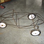
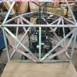
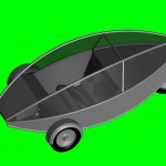
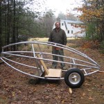
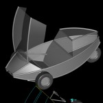
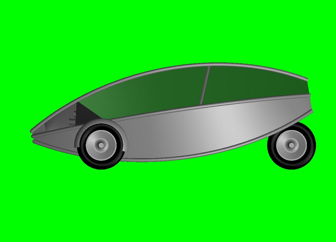
About a year ago (2007) I began to dream about building a car that would embody, what I believe are the most basic common sense features of light weight and economy, and so, my ROOPOD project was born!
Here are some pictures and drawings of ROOPOD progress: Check it out, I add new pictures often…subscribe to the feed, you will see when it is done! NOTE: if you want to see a bigger picture of any of the pics in the blog look at the gallery at the end of the post…you can click on a thumbnail for a bigger view.
3/4/09
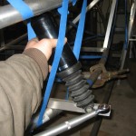
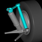
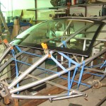
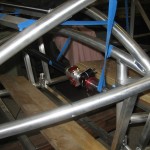
check out the new pictures! I have started to mount the front suspension perches and build the arms/ spindles/ shock mounts etc the shocks are from the rear end of a Harley “bagger” chosen for their’ air-adjust-ability and small size they have 3″ of travel, giving me a bit over 4″ total wheel travel. The biomorphic looking suspension arms will be 3d machined from 6061 solid “hate the word billet”
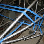
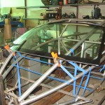
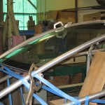
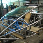
also look at the pictures of the windshield, this is the stock unit from a VW New Beetle and I built the frame to have about the same curves…I just have to cut the sides off! If anyone has the “killer” way to do this without ruining the windshield, please let me know! I am very happy with the way that the windshield looks with it’s compound curves etc, but I will have to make the hood and the “roof” behind the windshield with those same compound curves and that means learning to use the English wheel…wish me luck…
next up, the cross bars that run across the floor between the lower “A” arm perches and then the floor…
3/8/09
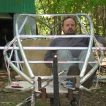
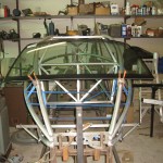
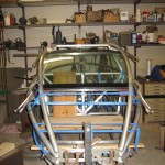
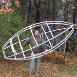
I am posting a pic with the canopy raised for people wondering how you get into roopod…
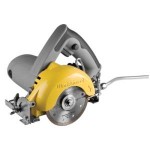
I also ordered a handheld tile saw from home depot that I saw recommend on a “rodding” blog as a good way to cut the windshield down…it has a 4″ diamond blade and looks like a small skillsaw…it is used with water coolant will practice on my “practice” free windshield hope it works, it was about $100…
tile saw to cut down windshield
3/14/09
I received my saw,and have made some practice cuts, and it seems to work quite well…I will put some pics on shorly…still need to figure out a curved guide for the saw to make those big, sweeping curved cuts…it did cut great freehand curves…
4/1/09
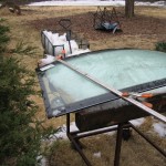
The good news…the bad news…I cut the windshield and I got the cuts just perfect…the bad news, I got several cracks along the cuts…the good news, I can use the windshield as a mock up, etc to keep building with, I will just have to figure out what went wrong…I am thinking that using a “fence” to cut along may have made the blade rub on the sides of the cut more, and that may have caused the cuts to crack…I made several cuts freehand in the left over pcs and got nary a crack…may have to “freehand” it on the next one…
I used snow…probably the last of the season, to provide a supportive bed for the glass as I cut it..
This is probably the problem…I bent a pc of alum to the shape of the curve, and the shape of the windshield and ran the saw along it…it probably made the blade rub on the sides of the cut and heat up too much…
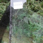
This is the pc I cut off
Windshield in place, my cuts were right on! oh well I think it is going to look pretty cool!
front view of the windshield fits just perfect…
you can see that the curve is just a bit more shallow than the curve of the tube, but it is close enough…now, just make those cracks go away!
4/2/09
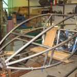
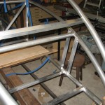
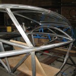
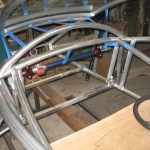
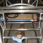
I got a bunch of frame work done today…I cut and installed two floor cross pieces, the main dash cross piece and the curved piece that holds the front of the windshield…also the two pieces that run vertically to form the “pocket” that the shock fits into…
you can see all the installed pieces in this pic…next will be the side pieces that go from the dash cross piece to the bottom of the windshield pc…and the rest of the frame for the “canopy”
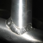
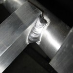
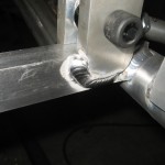
A typical weld…not the best in the world…but better than some of the other ones!
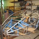
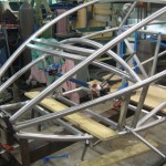
another view of the frame…there will be a heavy tube from the bottom of the two verticals to 4″ in on the dash cross-piece to brace the shock loads…
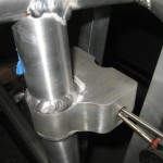
another weld…
I taped up some of the spaces, so I could see if everything will fit…rack goes right under dash….and 4 gallons of fuel, radiator, battery and heater core/fan fuse panel headlights etc…there will be no extra room in the dash/hood area….but we need as much weight as possible in the front…the loose tube is for the “side impact” door beam…it will go from the top of the front shocks to the rear swing arm pivot…
4/3/09
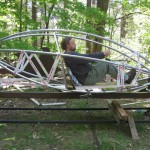
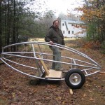
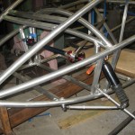
I took the frame off the jig for the first time today!…roopod looks so much smaller when it’s down on the ground…I am stepping in to show the step-over when you get in…
looks short too! that’s the 145-80-r10 tire…seat to be upgraded…lol
this was one test that I was dying to do…I am guessing that there is about 100lb of aluminum in the frame so far…I don’t have my scale handy, but it was not too hard to hold while my daughter took the picture!
4/7/09
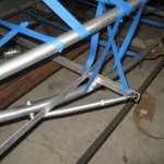
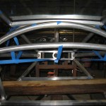
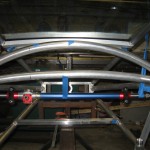
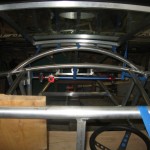
I just got done with removing the old strait-across dash beam, and put this double curved one in…the strait-across version was too close to where my shins wanted to be…now there is plenty of room…the horizontal blue tape line is where the rack will be…it is several inches ahead of the dash, and therefor not a problem to be that low….
another view: this design makes the dash a very strong “truss” that will resist the loads twisting on the front end when one wheel hits a bump…not yet installed is the vertical tube that holds the actual shock mount it is about 3″ in from the side and directly below the arched dash beam…blue tape in this picture is to visualize the shape of the dash sheet metal…
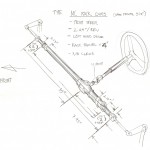
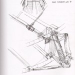
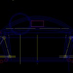
here is a drawing of the front suspension geometry…note the curved dash, and the vertical tubes that hold the inner pivots…go to this drawing in the “gallery” at the end of the post and click it two times to get a full size pic…
4/8/09
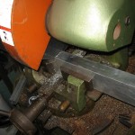
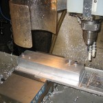
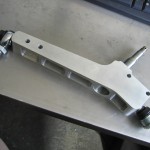
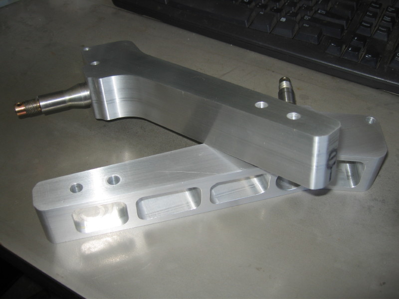
Am working on the front suspension today, these parts are the “uprights” some people would call them spindles…they will hold the actual spindles and link the upper and lower ball joints and hold the brake caliper, steering arm, and fender…guess they do alot…here is the 1.5″ x 3″ bar of 6061-t6 aluminum getting cut on the cold saw…
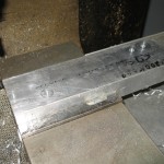
Cnc drilled the holes that will hold it down to the fixture plate, then later they will be used to mount the brake caliper hanger and steering arm…
block bolted to the fixture plate ready to be “profiled”
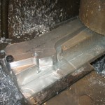
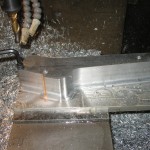
part starting to take shape: the 1/2″ end mill travels around the “countour” at 1/4″ deep intervals
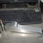
taking the part off…nice and smooth!
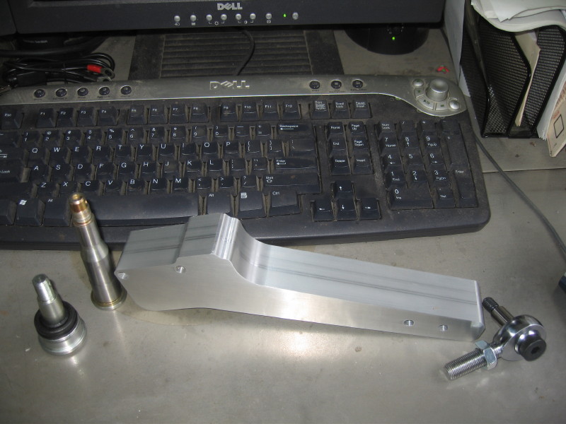
here is the part off the mill…polaris lower ball joint, and heim joint for the top, and the spindle that was removed from the polaris upright. next are the pockets for the spindle and the ball joint castle nut.
here is a youtube video of the cnc doing it’s thing…
4/13/09
[singlepic id=238 w=320 h=240 float=none]
here is the spindle bore being drilled…later to be reamed…
[singlepic id=235 w=320 h=240 float=none]
here are the pockets milled to lighten this thing up…the bar started about 4lb now down to about 1.5lb
now almost done, just have to make the tapered seats for the lower ball joints and the tapped hole for the heims at the top…
4/15/09
A lot done! here are some pics of work on the spindle upright…drilling, and reaming the tapered hole for the lower ball joint and the steps to get there, how I pressed in the spindles and a pic with the thing mounted to a wheel:
[singlepic id=241 w=320 h=240 float=none]
[singlepic id=242 w=320 h=240 float=none]
[singlepic id=244 w=320 h=240 float=none]
[singlepic id=245 w=320 h=240 float=none]
This is the upright almost done, all that is left is the pinchbolt for the upper ball joint screw (to lock it) and of course the brake caliper bracket and steering arm…
4/23/09
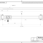
I ordered my rack!…here is the drawing from woodward…ships friday…also ordered a steering-splined shaft and u joint…can’t wait to get it…
4/28/09
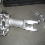
These are the upper suspension perches…they hold both the top of the shock and the upper A-Arm they get welded right into the frame…
[singlepic id=251 w=320 h=240 float=none]
[singlepic id=250 w=320 h=240 float=none]
[singlepic id=252 w=320 h=240 float=none]
4/30/09
Here is a pic of the upper and lower front suspension perches…on a sample tube…they will be welded to that tube and to other frame tubes…
5/1/09
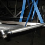
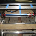
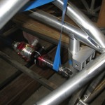
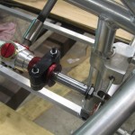
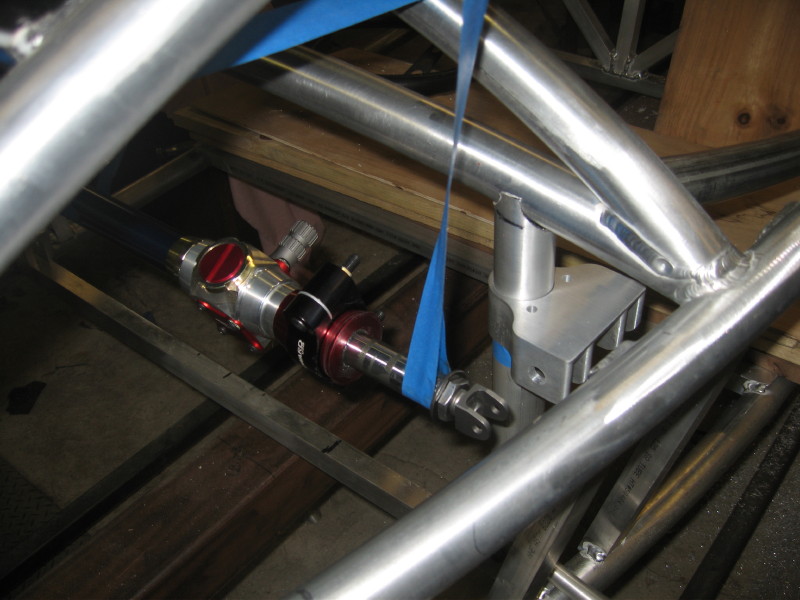
The “RACK” came in..yay!!! here are some pics with the rack about where it will go and also some details of how the suspension perches and diagonal braces (armrests) will mount…time to do some welding soon!
from the front…
Driver’s view
Note the “armrest” braces coming in to the dashboard tube…I think this will help triangulate the top of the frame
5/29/09
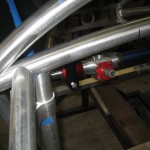
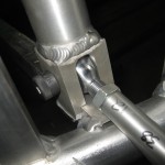
Finally! some more work done, I did not get to take a pic of all the steps..too much of a hurry…but here is the results: the front suspension perches are all in, and mosstly welded…there are a few gussets to add and the like, but mostly it’s done…these pictures show the rack where it will mount, and I will be able to attach the wheels as soon as I make the upper and lower control arms…too much “regular work”!
note here (below) that the upper perches are for the upper arms and the top of the shock…
this is the lower perch…you can see the .5″ heim here…
the other side
side view…you can see the “slot” that the shock fits into…
2/5/09
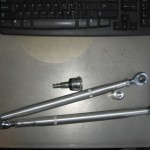
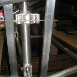
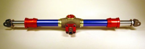
I know this is out of order, but I will fix it later…but this is the rack and pinion steering unit that I am going to use:
they will build it to my specs: cost: about $700.00! yikes, but it will be nice…Doug Milliken suggested this one.
This is a gallery of all the pictures in the post...if you click on the pic, you can get a full sized picture if you want to see more detail...
roopod Early scale study
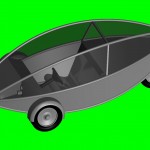
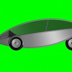
roopod side view pass. fit
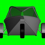
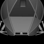
roopod front view pass. fit
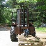
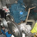
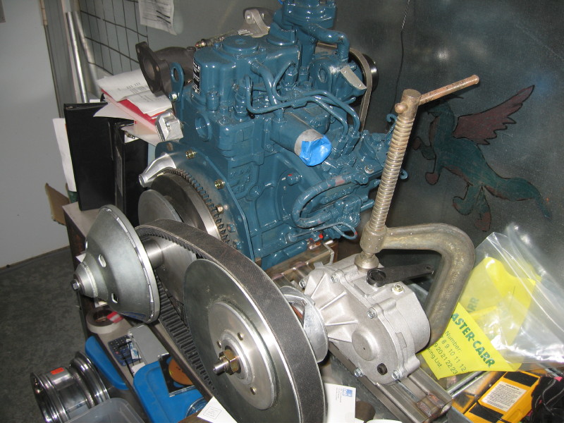
power plant on the way to roopod
kubota z482 where it will go in roopod
roopod headlights
roopod lights
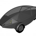
roopod 7/19/08 rendering w/steering wheel
roopod
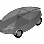
roopod side view
roopod top view
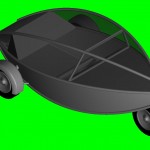
roopod 3/4 rear veiw
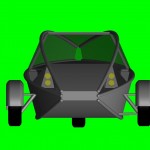
roopod rear view
roopod front view
12″ x 1/2-20 radius rods and 1/2″ Heims + polaris ball joint
Heim joint
Heim Joint
Radius rod 1/2″ Heim joint to be welded
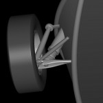
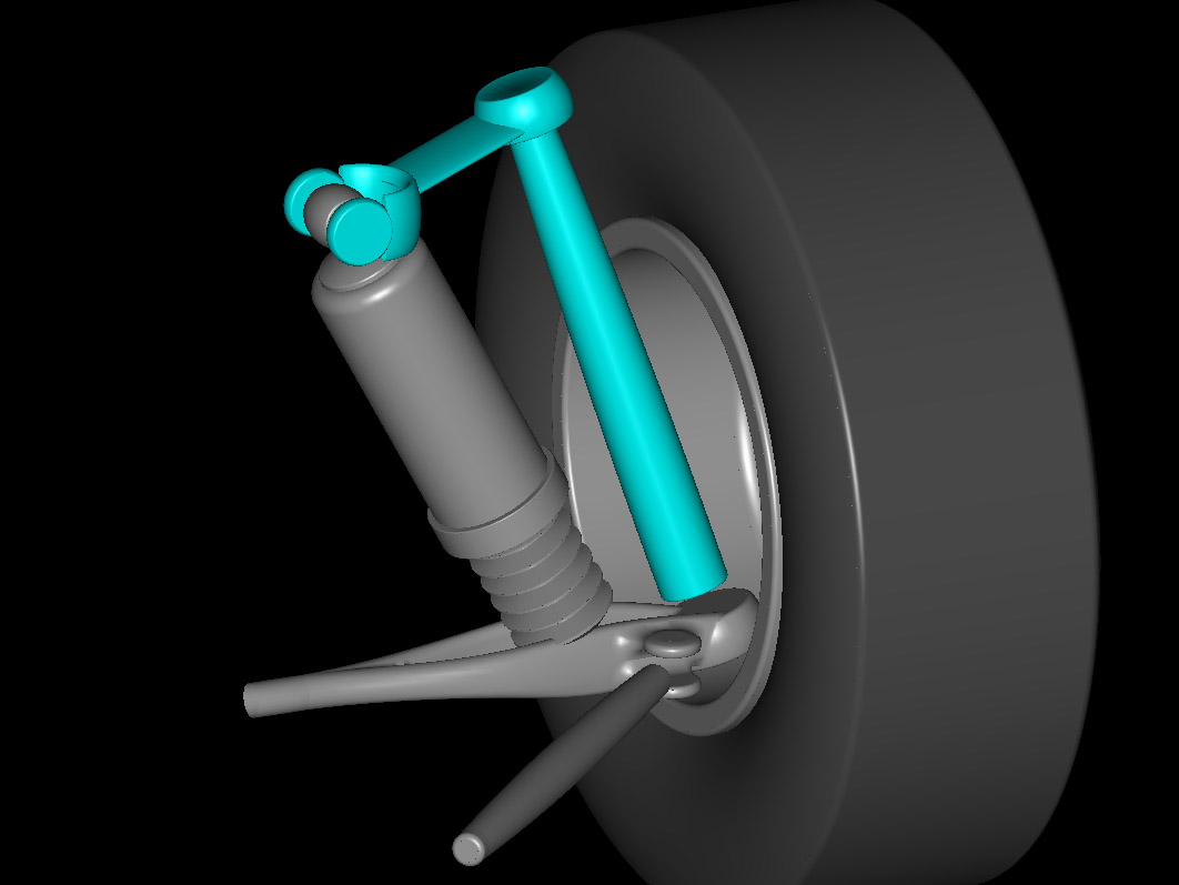
Front Suspension radius rod and shock position
front suspension design cad rendering
worms eye view of front suspension
Front Suspension basic idea for spindle upper a arm
Kubota Z482 with Comet 94C CVT and Comet FNR Gearbox
VW New Beetle windshield gets cut down to fit between frame rails
New Beetle Windshield
windshield to cut down
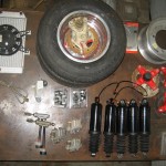
Varios parts for roopod harley shocks, polaris brakes, radiator, hubs, ball joints, tie rod ends Khumho tires 10-145-80
This page will evolve as I build ROOPOD, but I will put down what I specs there are at this point.
Frame/Body:
6061 t651 aluminum throughout main tubes 1.5″ X .125″ wall bulkhead square tubes 1″ X .125″ body “skin” .060″ sheet. Frame completely joined by TIG welding using 4046 wire and 100% argon. Whole body to be heat treated at www.countyheattreat.com after all welding is completed (to restore anealed areas caused by welding) complete body to be in the 200lb range.
Suspension:
Tires:145/80R 10’s 19.1″ diameter (used on the clasic Mini Cooper) (Khumho brand)
Rear shocks: Air-Coil spring adjustable shocks from the rear of a Harley “bagger”
Steering: woodward rack and pinion manual
Powertrain:
Kubota Z482 with Comet 94C CVT and Comet FNR Gearbox
Kubota z482 water cooled two cylinder Diesel engine 482 cc 12hp @ 3600rpm
(I may see about adding a turbocharger to this if it is too wimpy)
Comet variable belt Transmission “94C-Duster”
NOVA RACING Reverse gearbox custom to match comet CVT
Chain final drive +/- 4:1 (520 chain-roopod built rear sprocket)
polaris “preadator 500” radiator, front mounted
Heated fuel tank: ROOPOD made (to enable SVO use and b100 winter use) 3 gal
Starting fuel tank: ROOPOD made(to hold petro diesel for starting) 3 gal
Body Features:
Windshield: middle portion of a VW New Beetle windshield cut-down
Side-rear windows: .125″ Marguard lexan
Headlights: Hella 2.375″ modular projecters two high/two low beam
Directional/tail/brake lights: LED ROOPOD built
Door: ROOPOD made hinged along dashboard, gas strut supported.
Heater: heater core/ variable fan dash mounted/ servo control valve
Legal:
ROOPOD: will be registered in Massachusetts as a motorcycle, it will bear the vin from a donor bike, and in the eyes of the state, will be that motorcycle that I have “modified” I have talked to someone who has done this, and it worked for them…keeping my fingers crossed! I am hoping that I can get away without having to require helmet use…insurance will cover it as a modified motorcycle.
this is where I will put all the interesting pics and other stuff, and what I think of it…Roo
here is a article in the New York TImes, that talks about three wheels to save gas. kindly sent to me by David and Natalie Hanna…I am not quite so regular in my ‘Times reading!
I am building roopod out of aluminum for it’s durabilty and recyclabilty…and mostly trying to use as little (aluminum) as possible (by making roopod as light as possible)
Help support my project/ become a sponsor! Please contact me if you would like to help prove to everybody that a great, green and efficient car can be created right here at home!
HI there everybody! (8/17/08)
ROOPOD has it’s first sponsor! Ben Licata, of Northfield, MASS has contributed an old bike with a good title that will be reborn as ROOPOD! Just so you know…it is a 1980 Kawasaki KZ44A2 (440cc) and probably the only thing that will make it onto ROOPOD will be the VIN! Thanks Ben, your help is really appreciated.
Hi again (2/17/09)
the countless pieces of advice from so many people: thanks to you all, I will mention names when I check and see if you all care! but many thanks you know who you are…
(7/30/09)
REBEL WIRE (http://www.rebelwire.com/) Has contributed a complete wire harness for the roopod! many thanks to Bob Miller at REBEL WIRE!
Disclaimer: I know full well that the best vehicle there is to be had is no vehicle, then one that burns no fuel, but barring those options (walking and biking come hard to a lazy oaf like me) I Just had to start thinking about this car problem!
It all started one day, when I came across the sticker inside the door of my VW New Beetle…it said…3,704 gvrw…that’s how much it’s supposed to weigh fully loaded…3 passengers, the driver and fuel/cargo etc…
Then I thought, yikes! For a small car, when I drive this car myself…I can take about 600lb off that weight and get about 3100lb actual weight …I am dragging around just under 3000lb of car just to carry my 250lb body around…I am not so hot at math, but if you divide say 2800 by 250 you get a ratio of 11.2:1 and then I realized, out of my 1 gallon of gas I buy for this car, I use 11 parts to carry the car around, to the one part that is used to carry my weight. If I add a passenger, I do a little better, even another big guy like me…lets say 500lb and that brings the weight up to 3050lb so that ratio is 6.1:1 a lot better but still six parts of my gallon of gas goes to move the car around…! I won’t even talk about more passengers as it is incredibly rare to carry more than one…
I thought: I can do better than that! I think I can build something that will get me around, in relative safety and comfort and improve that ratio a whole hell of a lot! Then the head scratching began. My eventual goal…A ratio of 1:1 with two people in my vehicle…my numbers would go like this…very simple…250X2 (two of me) (500) that gave me how much my car would get to weigh 500lb. If I am just in the car then my ratio will be 2:1 so very much better than my VW!


