Jul 15, 2008
construction progress blog
Categories: featured
Written By: roo
Here are some pictures and drawings of ROOPOD progress: Check it out, I add new pictures often...subscribe to the feed, you will see when it is done! NOTE: if you want to see a bigger picture of any of the pics in the blog look at the gallery at the end of the post...you can click on a thumbnail for a bigger view.
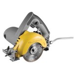
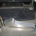
 I also ordered a handheld tile saw from home depot that I saw recommend on a "rodding" blog as a good way to cut the windshield down...it has a 4" diamond blade and looks like a small skillsaw...it is used with water coolant will practice on my "practice" free windshield hope it works, it was about $100...

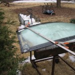
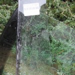
 I used snow...probably the last of the season, to provide a supportive bed for the glass as I cut it..
 This is probably the problem...I bent a pc of alum to the shape of the curve, and the shape of the windshield and ran the saw along it...it probably made the blade rub on the sides of the cut and heat up too much...
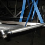
 This is the pc I cut off
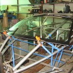
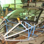
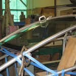
 Windshield in place, my cuts were right on! oh well I think it is going to look pretty cool!
 front view of the windshield fits just perfect...
 you can see that the curve is just a bit more shallow than the curve of the tube, but it is close enough...now, just make those cracks go away!
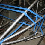
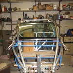
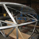
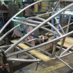
 you can see all the installed pieces in this pic...next will be the side pieces that go from the dash cross piece to the bottom of the windshield pc...and the rest of the frame for the "canopy"
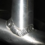
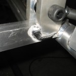
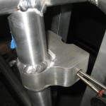
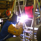
 A typical weld...not the best in the world...but better than some of the other ones!
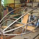
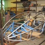
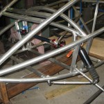
 another view of the frame...there will be a heavy tube from the bottom of the two verticals to 4" in on the dash cross-piece to brace the shock loads...
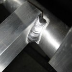
 another weld...
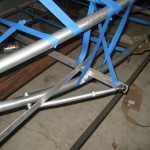
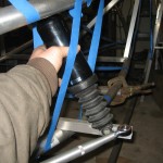
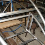
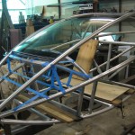
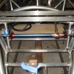
 I taped up some of the spaces, so I could see if everything will fit...rack goes right under dash....and 4 gallons of fuel, radiator, battery and heater core/fan fuse panel headlights etc...there will be no extra room in the dash/hood area....but we need as much weight as possible in the front...the loose tube is for the "side impact" door beam...it will go from the top of the front shocks to the rear swing arm pivot...
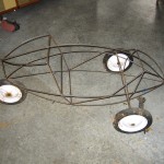
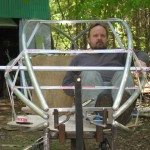
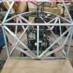
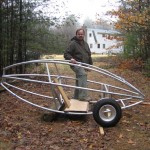
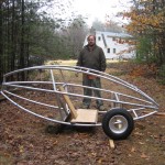
 I took the frame off the jig for the first time today!...roopod looks so much smaller when it's down on the ground...I am stepping in to show the step-over when you get in...
 looks short too! that's the 145-80-r10 tire...seat to be upgraded...lol
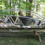
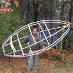
 this was one test that I was dying to do...I am guessing that there is about 100lb of aluminum in the frame so far...I don't have my scale handy, but it was not too hard to hold while my daughter took the picture!
 I just got done with removing the old strait-across dash beam, and put this double curved one in...the strait-across version was too close to where my shins wanted to be...now there is plenty of room...the horizontal blue tape line is where the rack will be...it is several inches ahead of the dash, and therefor not a problem to be that low....
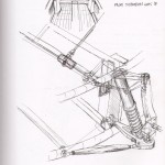
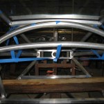
 another view: this design makes the dash a very strong "truss" that will resist the loads twisting on the front end when one wheel hits a bump...not yet installed is the vertical tube that holds the actual shock mount it is about 3" in from the side and directly below the arched dash beam...blue tape in this picture is to visualize the shape of the dash sheet metal...
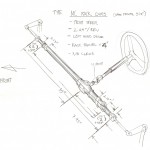
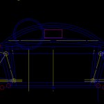
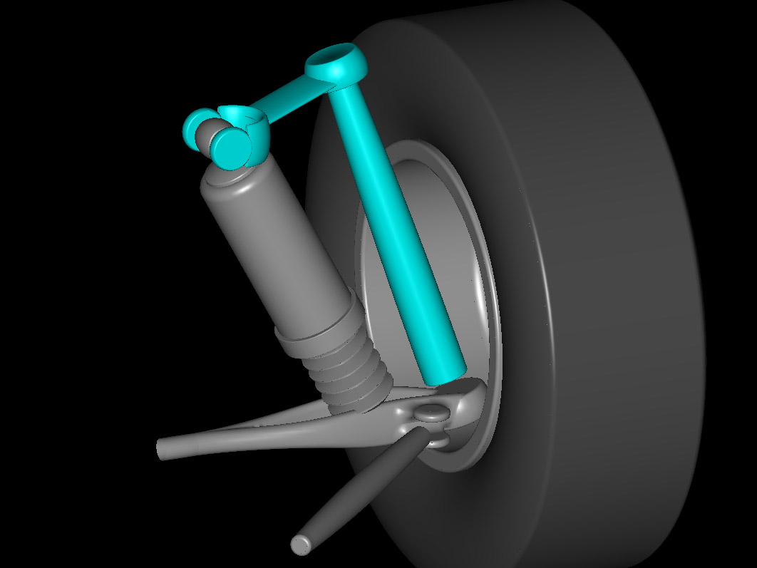
 here is a drawing of the front suspension geometry...note the curved dash, and the vertical tubes that hold the inner pivots...go to this drawing in the "gallery" at the end of the post and click it two times to get a full size pic...
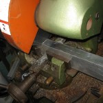
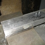
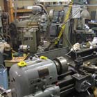
 Am working on the front suspension today, these parts are the "uprights" some people would call them spindles...they will hold the actual spindles and link the upper and lower ball joints and hold the brake caliper, steering arm, and fender...guess they do alot...here is the 1.5" x 3" bar of 6061-t6 aluminum getting cut on the cold saw...
 Cnc drilled the holes that will hold it down to the fixture plate, then later they will be used to mount the brake caliper hanger and steering arm...
 block bolted to the fixture plate ready to be "profiled"
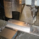
 part starting to take shape: the 1/2" end mill travels around the "countour" at 1/4" deep intervals
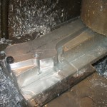
 taking the part off...nice and smooth!
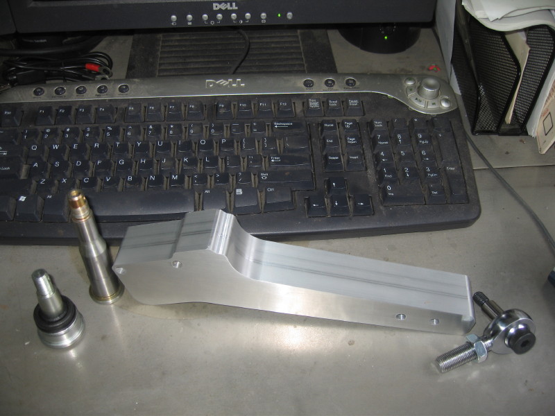
 here is the part off the mill...polaris lower ball joint, and heim joint for the top, and the spindle that was removed from the polaris upright. next are the pockets for the spindle and the ball joint castle nut.
here is a youtube video of the cnc doing it's thing...
here is the part off the mill...polaris lower ball joint, and heim joint for the top, and the spindle that was removed from the polaris upright. next are the pockets for the spindle and the ball joint castle nut.
here is a youtube video of the cnc doing it's thing...
 here is the spindle bore being drilled...later to be reamed...
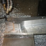
 here are the pockets milled to lighten this thing up...the bar started about 4lb now down to about 1.5lb
 now almost done, just have to make the tapered seats for the lower ball joints and the tapped hole for the heims at the top...


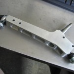
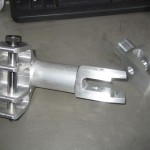
 This is the upright almost done, all that is left is the pinchbolt for the upper ball joint screw (to lock it) and of course the brake caliper bracket and steering arm...


 Driver's view


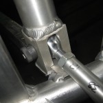
 Note the "armrest" braces coming in to the dashboard tube...I think this will help triangulate the top of the frame

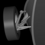
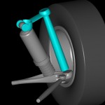
 note here (below) that the upper perches are for the upper arms and the top of the shock...
 this is the lower perch...you can see the .5" heim here...
 the other side

 side view...you can see the "slot" that the shock fits into...

3/4/09
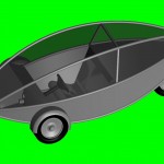
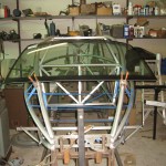
check out the new pictures! I have started to mount the front suspension perches and build the arms/ spindles/ shock mounts etc the shocks are from the rear end of a Harley "bagger" chosen for their' air-adjust-ability and small size they have 3" of travel, giving me a bit over 4" total wheel travel. The biomorphic looking suspension arms will be 3d machined from 6061 solid "hate the word billet" also look at the pictures of the windshield, this is the stock unit from a VW New Beetle and I built the frame to have about the same curves...I just have to cut the sides off! If anyone has the "killer" way to do this without ruining the windshield, please let me know! I am very happy with the way that the windshield looks with it's compound curves etc, but I will have to make the hood and the "roof" behind the windshield with those same compound curves and that means learning to use the English wheel...wish me luck... next up, the cross bars that run across the floor between the lower "A" arm perches and then the floor...3/8/09
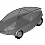
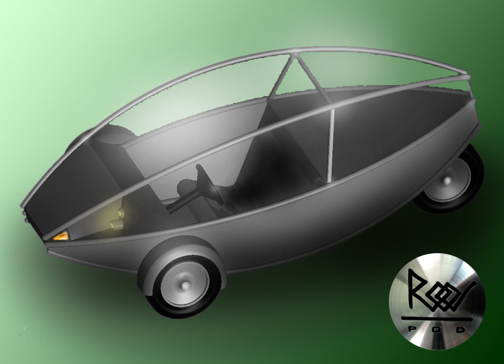
I am posting a pic with the canopy raised for people wondering how you get into roopod...
I also ordered a handheld tile saw from home depot that I saw recommend on a "rodding" blog as a good way to cut the windshield down...it has a 4" diamond blade and looks like a small skillsaw...it is used with water coolant will practice on my "practice" free windshield hope it works, it was about $100...
tile saw to cut down windshield
3/14/09
I received my saw,and have made some practice cuts, and it seems to work quite well...I will put some pics on shorly...still need to figure out a curved guide for the saw to make those big, sweeping curved cuts...it did cut great freehand curves...4/1/09
The good news...the bad news...I cut the windshield and I got the cuts just perfect...the bad news, I got several cracks along the cuts...the good news, I can use the windshield as a mock up, etc to keep building with, I will just have to figure out what went wrong...I am thinking that using a "fence" to cut along may have made the blade rub on the sides of the cut more, and that may have caused the cuts to crack...I made several cuts freehand in the left over pcs and got nary a crack...may have to "freehand" it on the next one...
I used snow...probably the last of the season, to provide a supportive bed for the glass as I cut it..
This is probably the problem...I bent a pc of alum to the shape of the curve, and the shape of the windshield and ran the saw along it...it probably made the blade rub on the sides of the cut and heat up too much...
This is the pc I cut off
Windshield in place, my cuts were right on! oh well I think it is going to look pretty cool!
front view of the windshield fits just perfect...
you can see that the curve is just a bit more shallow than the curve of the tube, but it is close enough...now, just make those cracks go away!
4/2/09
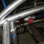
I got a bunch of frame work done today...I cut and installed two floor cross pieces, the main dash cross piece and the curved piece that holds the front of the windshield...also the two pieces that run vertically to form the "pocket" that the shock fits into...
you can see all the installed pieces in this pic...next will be the side pieces that go from the dash cross piece to the bottom of the windshield pc...and the rest of the frame for the "canopy"
A typical weld...not the best in the world...but better than some of the other ones!
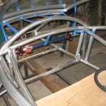
another view of the frame...there will be a heavy tube from the bottom of the two verticals to 4" in on the dash cross-piece to brace the shock loads...
another weld...
I taped up some of the spaces, so I could see if everything will fit...rack goes right under dash....and 4 gallons of fuel, radiator, battery and heater core/fan fuse panel headlights etc...there will be no extra room in the dash/hood area....but we need as much weight as possible in the front...the loose tube is for the "side impact" door beam...it will go from the top of the front shocks to the rear swing arm pivot...
4/3/09
I took the frame off the jig for the first time today!...roopod looks so much smaller when it's down on the ground...I am stepping in to show the step-over when you get in...
looks short too! that's the 145-80-r10 tire...seat to be upgraded...lol
this was one test that I was dying to do...I am guessing that there is about 100lb of aluminum in the frame so far...I don't have my scale handy, but it was not too hard to hold while my daughter took the picture!
4/7/09
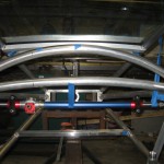
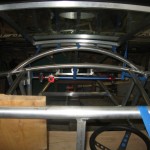
I just got done with removing the old strait-across dash beam, and put this double curved one in...the strait-across version was too close to where my shins wanted to be...now there is plenty of room...the horizontal blue tape line is where the rack will be...it is several inches ahead of the dash, and therefor not a problem to be that low....
another view: this design makes the dash a very strong "truss" that will resist the loads twisting on the front end when one wheel hits a bump...not yet installed is the vertical tube that holds the actual shock mount it is about 3" in from the side and directly below the arched dash beam...blue tape in this picture is to visualize the shape of the dash sheet metal...
here is a drawing of the front suspension geometry...note the curved dash, and the vertical tubes that hold the inner pivots...go to this drawing in the "gallery" at the end of the post and click it two times to get a full size pic...
4/8/09
Am working on the front suspension today, these parts are the "uprights" some people would call them spindles...they will hold the actual spindles and link the upper and lower ball joints and hold the brake caliper, steering arm, and fender...guess they do alot...here is the 1.5" x 3" bar of 6061-t6 aluminum getting cut on the cold saw...
Cnc drilled the holes that will hold it down to the fixture plate, then later they will be used to mount the brake caliper hanger and steering arm...
block bolted to the fixture plate ready to be "profiled"
part starting to take shape: the 1/2" end mill travels around the "countour" at 1/4" deep intervals
taking the part off...nice and smooth!
here is the part off the mill...polaris lower ball joint, and heim joint for the top, and the spindle that was removed from the polaris upright. next are the pockets for the spindle and the ball joint castle nut.
here is a youtube video of the cnc doing it's thing...
4/13/09


4/15/09
A lot done! here are some pics of work on the spindle upright...drilling, and reaming the tapered hole for the lower ball joint and the steps to get there, how I pressed in the spindles and a pic with the thing mounted to a wheel:


 This is the upright almost done, all that is left is the pinchbolt for the upper ball joint screw (to lock it) and of course the brake caliper bracket and steering arm...
4/23/09
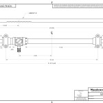
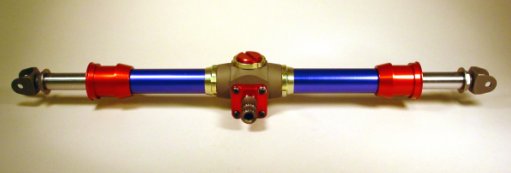
I ordered my rack!...here is the drawing from woodward...ships friday...also ordered a steering-splined shaft and u joint...can't wait to get it...
4/28/09
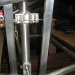
These are the upper suspension perches...they hold both the top of the shock and the upper A-Arm they get welded right into the frame...


4/30/09
Here is a pic of the upper and lower front suspension perches...on a sample tube...they will be welded to that tube and to other frame tubes...
5/1/09
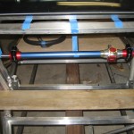
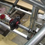
The "RACK" came in..yay!!! here are some pics with the rack about where it will go and also some details of how the suspension perches and diagonal braces (armrests) will mount...time to do some welding soon! from the front...
Driver's view
Note the "armrest" braces coming in to the dashboard tube...I think this will help triangulate the top of the frame
5/29/09
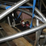
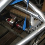
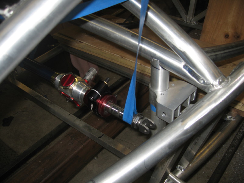
Finally! some more work done, I did not get to take a pic of all the steps..too much of a hurry...but here is the results: the front suspension perches are all in, and mosstly welded...there are a few gussets to add and the like, but mostly it's done...these pictures show the rack where it will mount, and I will be able to attach the wheels as soon as I make the upper and lower control arms...too much "regular work"!
note here (below) that the upper perches are for the upper arms and the top of the shock...
this is the lower perch...you can see the .5" heim here...
the other side
side view...you can see the "slot" that the shock fits into...
2/5/09
I know this is out of order, but I will fix it later...but this is the rack and pinion steering unit that I am going to use: they will build it to my specs: cost: about $700.00! yikes, but it will be nice...Doug Milliken suggested this one.

This is a gallery of all the pictures in the post...if you click on the pic, you can get a full sized picture if you want to see more detail...
-
-
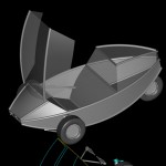
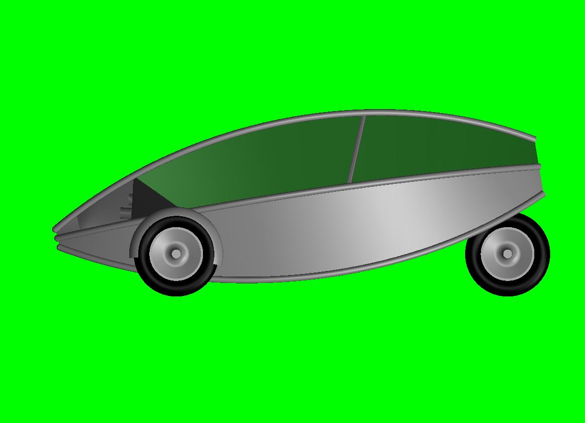
roopod Early scale study
-
-
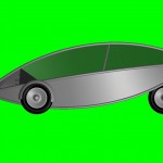
roopod side view pass. fit
-
-
roopod front view pass. fit
-
-
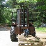
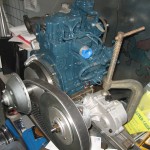
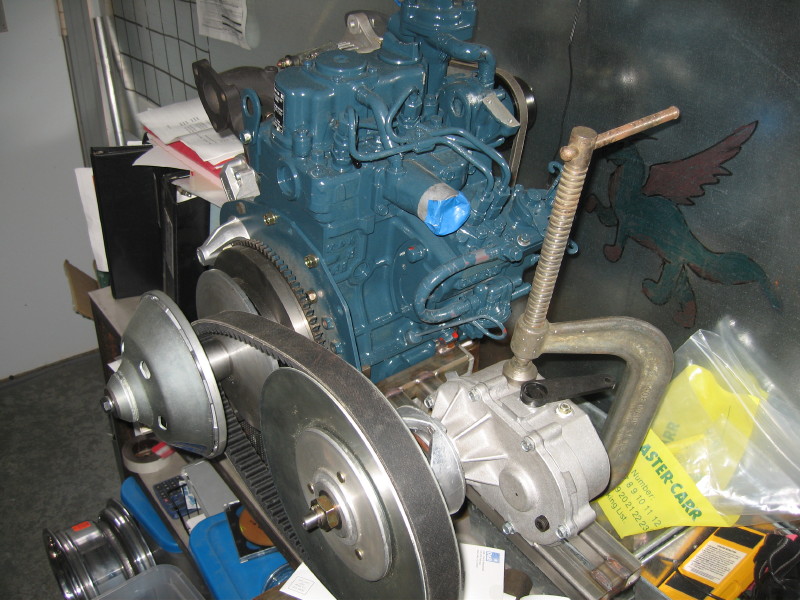
power plant on the way to roopod
-
-
kubota z482 where it will go in roopod
-
-
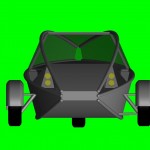
roopod headlights
-
-
roopod lights
-
-
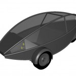
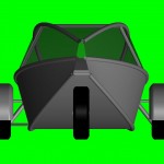
roopod 7/19/08 rendering w/steering wheel
-
-
roopod
-
-
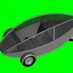
roopod side view
-

-
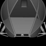
roopod top view
-
-
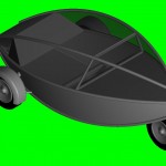
roopod 3/4 rear veiw
-
-
roopod rear view
-
-
roopod front view
-
-
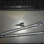
12″ x 1/2-20 radius rods and 1/2″ Heims + polaris ball joint
-
-
Heim joint
-
-
Heim Joint
-
-
Radius rod 1/2″ Heim joint to be welded
-
-
Front Suspension radius rod and shock position
-
-
front suspension design cad rendering
-
-
worms eye view of front suspension
-
-
Front Suspension basic idea for spindle upper a arm
-
-
Kubota Z482 with Comet 94C CVT and Comet FNR Gearbox
-
-
VW New Beetle windshield gets cut down to fit between frame rails
-
-
New Beetle Windshield
-
-
windshield to cut down
-
-
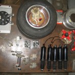
Varios parts for roopod harley shocks, polaris brakes, radiator, hubs, ball joints, tie rod ends Khumho tires 10-145-80
-

-
-
tile saw to cut down windshield
-
-
-
-
-
-

-
-
-
-
-
-
-
-
-
-
-
-
-
-
-
-
-
-
-
-
-
-
-
-
-
-
-
-
-
-
-
-
-
-
-
-
-
-

-
-


July 9th, 2008 at 7:04 pm
Hi Roo,
The frame for the pod looks great. I can’t wait to see it!!
fc
July 10th, 2008 at 12:58 am
Roopod.com is looking fantastic Roo! Seriously good work! Keep it up!
July 11th, 2008 at 12:13 pm
In the future all will be pod [industrial design humor]:
http://www.coroflot.com/public/individual_file.asp?sort_by=1&portfolio_id=169392&individual_id=120719
August 14th, 2008 at 3:09 pm
Roo, did you say one or two passengers might work? – thinking of transporting all our kidlets
September 10th, 2008 at 12:01 am
That’s cool, Roo! I gather it’ll be fwd? What are you figuring/predicting for weight?
March 4th, 2009 at 1:15 pm
Hoooooooot shit!!!! the roopod is moving again! i gotta get up there and see it! what is the plan for getting in and out?
Keep on truckin, roo! jory
April 11th, 2009 at 5:43 am
Hey, Check out the cnc machining an “upright” some will think “watching a pot boil” but, never the less…
April 25th, 2009 at 12:53 pm
It’s really amazing to see what you are doing. You are on the cutting edge of what the future of cars will be. Fred and I love your machine pics. You have a great workshop to create this masterpiece. Keep up the great work…….your sister-in-law
August 20th, 2009 at 4:51 am
BURNING THE MIDNITE OIL. GOOD LUCK AND HAPPY MOTORING.
BOB
October 13th, 2009 at 8:23 pm
Checking back with your progress. I see from the pictures that you now have cut that windshield glass! Did you end up cutting it with that tile saw? According to my glass man, cutting it with a tile saw would create too much heat and perhaps cause cracks but my thinking is that if you added coolant while doing it and went slow, it still should work. Is that how it went? However you did it, congrats. I’m just really curious how you finally did it? Let me know, OK? I know these kinds of projects can take a while, especially if you have another life! Looks like you’ve made good progress though!
Will, the Tink
Ubuntu 9.04
N45°29’05, W122°19.20
January 8th, 2010 at 5:48 pm
I’m working as a marble and granite mason- my art was in glass some years ago and I’ve friends who work stone -semi precious. A tile saw runs to hot even with water fed to the cut, and the grit is to course. I’d recommend you get a saw blade for a gem saw, mount it on a variable speed sander and cut slowly. The experianced glass cutters will cut laminated glass with a standard (little wheel) glass cutter, by scoring the glass on both sides and flexing the glass fracturing along the score lines, then cutting the plastic laminant with a knife. the edge needs polishing.
April 13th, 2010 at 10:49 pm
Wow, thanks for all the advice…I will try again in a few weeks!
December 7th, 2010 at 11:21 pm
I hope ROOPOD is coming along nicely. Its great that there are those who value the earth like you. Good luck and the vehicle is just classy.
July 31st, 2011 at 1:52 pm
How are things going? What’s the status of the vehicle? Hope all’s well.
August 12th, 2011 at 2:33 pm
The windshield cracked for a few reasons, you had the heat and the vibration problem, as well as sitting it on the snow with the heat of the saw created an expansion on one side and contraction on the other. If you want to do it right, send it to a cnc waterjet. Cool temperature, you can get a perfect size cut due to import of the solidworks (SLD) file, and you can put in small radius on the corners, as well as on completion you will have a finished edge. You can do a test cut with the old windshield to see if it works well. It would be probably not much more expensive then a new saw and blade.
March 6th, 2012 at 9:53 pm
Interesting project. I like the windshield.