Jul 16, 2009
LOWER A ARMS, REAR PIVOTS, FRONT WHEELS
Categories: Construction Progress
Written By: roo
here is a pic of the lower a arms, or control arms...still on the milling machine..I am checking the fit of that radius-rod clevis in the picture..
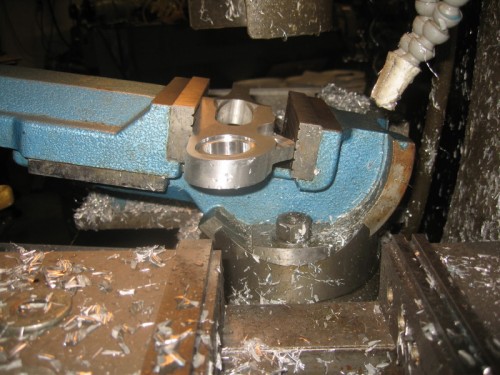
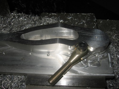 Here is a pic of the setup to bore the lower ball joint socket...I had to drag out the angle vise for this one! these arms were by the far the most complicated of the parts I have made so far...there were 6 different setups involved, 3d surfaces on two sides, and the angular setup you see here!
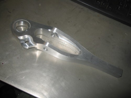
 the lower arms ready to have the ball joints pressed in! the relief on the inside is where the rubber boot of the shock goes..
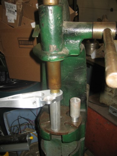
 the setup for pressing in the ball joints...I was worried about getting the press fit right, but it fit just right...not to hard...not to easy!
 THE WHEELS ARE ON THE CAR!!! Finally, next will be to replace the blue tape and wire steering arms and tie rods!
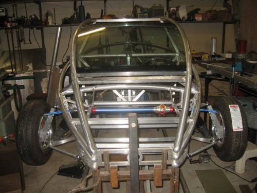 view from above...this is the view you will get when the car is off the jig, and on the ground, makes it look smaller!
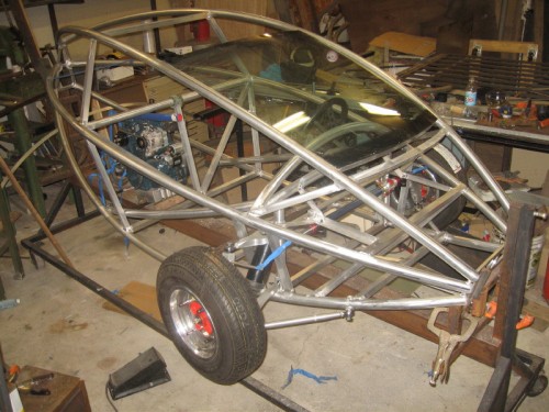 rear view...this shows what I call the "armrest tubes", they are also the side impact door beams, and the bottom end is the mount for the 1/2" heims for the rear swingarm pivots...I like the way they look...kinda wraps the dash around a bit...
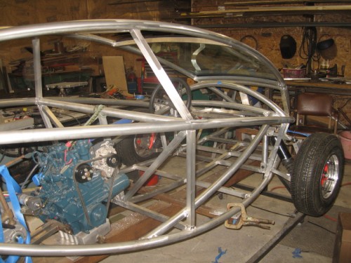 the front suspension...with the rack and pinion
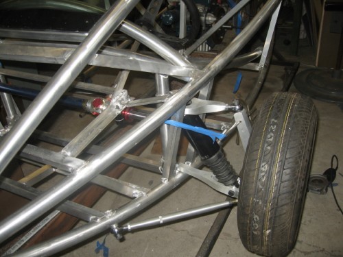 another view, I think that the "upright" looks a bit "clunky" compared to the upper and lower arms...The heims that are on in this pic are to be replaced with "high misalighnment" ones...the regular ones don't quite have the travel they need...
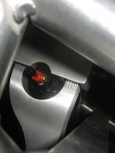
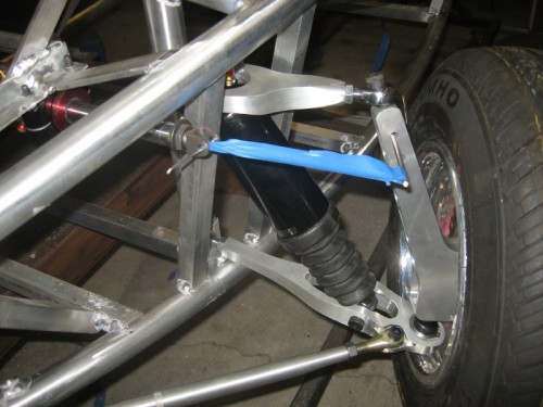 the air valve for the Harley shock...to fine tune the suspension spring rate...I had to make the upper arm wrap around the top of the shock, as the same shoulder bolt holds the upper shock mount, and the pivot for the upper control arm...
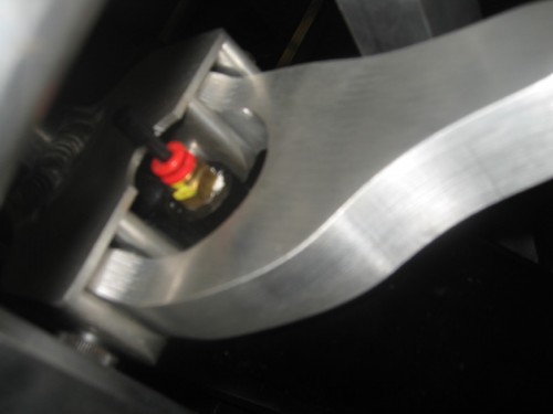 you can see the bottom of the ball joint here...dont want to forget that locknut of the the clevis bolt!
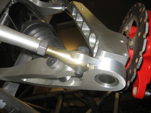 here is the upright turned as far as it can go...when the steering arm is in place it will not go quite that far...
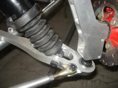 NEXT is the steering arms and tie rods, the the brakes!
 Here is a pic of the setup to bore the lower ball joint socket...I had to drag out the angle vise for this one! these arms were by the far the most complicated of the parts I have made so far...there were 6 different setups involved, 3d surfaces on two sides, and the angular setup you see here!
 the lower arms ready to have the ball joints pressed in! the relief on the inside is where the rubber boot of the shock goes..
 the setup for pressing in the ball joints...I was worried about getting the press fit right, but it fit just right...not to hard...not to easy!
 THE WHEELS ARE ON THE CAR!!! Finally, next will be to replace the blue tape and wire steering arms and tie rods!
 view from above...this is the view you will get when the car is off the jig, and on the ground, makes it look smaller!
 rear view...this shows what I call the "armrest tubes", they are also the side impact door beams, and the bottom end is the mount for the 1/2" heims for the rear swingarm pivots...I like the way they look...kinda wraps the dash around a bit...
 the front suspension...with the rack and pinion
 another view, I think that the "upright" looks a bit "clunky" compared to the upper and lower arms...The heims that are on in this pic are to be replaced with "high misalighnment" ones...the regular ones don't quite have the travel they need...
 the air valve for the Harley shock...to fine tune the suspension spring rate...I had to make the upper arm wrap around the top of the shock, as the same shoulder bolt holds the upper shock mount, and the pivot for the upper control arm...

 you can see the bottom of the ball joint here...dont want to forget that locknut of the the clevis bolt!
 here is the upright turned as far as it can go...when the steering arm is in place it will not go quite that far...
 NEXT is the steering arms and tie rods, the the brakes!
